4.3.5.3. SA3A3D (Small sized-6 axes integral type-driving apparatus)
4.3.5.3. SA3A3D (Small sized-6 axes integral type-driving apparatus)
The drive unit plays a role of amplifying power by sending current to each motor according to the current command from the servo board. The 6 axis all-in-one drive unit can operate 6 motors at the same time, and the following Table shows its components.
A small sized-diode module converter is formed integrally with a small-sized servo amplifier, and converts three-phase current provided from an electronic field module to direct current through the rectification of a diode module so as to store it in a smoothing capacitor. When the speed of the robot is reduced, power generated from a motor is consumed through a transistor and resistance. The diode module converter is constructed as shown below.
Table 4‑49 Construction of SA3A3D (Small sized-6 axes integral type-driving apparatus)
Component | Function | |
BD553 (IPM board) | Gate Drive Module | Generation of IPM gate signals |
Gate Power Module | Generation of gate power | |
Current Detection Unit | Detection of the current flowing into the motor | |
BD563 (Converter Board) | Rectifier Unit | Generation of DC power circuit provided from the AC input main power. |
Regenerative Control | Drive of IGBT if PN voltage increases | |
Error Detection Unit | The detection of overvoltage, overheated regenerative resistance, and bibliographic data input errors | |
Other Parts | Heat Sink | Emission of heat generated from IPM |
Capacitor | DC power smoothing | |
Regenerative IGBT | Execution of regenerative control | |
IPM | Switching Device | |
| Caution: As the drive unit varies depending on the robot, so please check out the form of it in replacing it. |


Figure 4.52 BD553 Component Layout
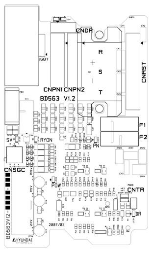
Figure 4.53 BD563 Component Layout
Table 4‑50 Description of connector BD553
Name | Use | External Device Connection |
CNBS1, 2, 3 | PWM Signal and Error Signal | Servo Board (BD542) CNBS1,2,3 |
CNSGA | /PWMON, SVERR, BRAKE | Sequence Board (BD530) CNSGA |
CNPWM7~8 | Additional Axis PWM Signal and Error Signal | Option Board (BD554, BD556) CNPWM |
CNM1~6 | Motor Connection | CMC1 |
CNPPNN | Power for motor drive | Drive Power Unit (BD561) CNPN1 |
CNFG | The frame ground of the Main Axis motor | CMC1 |
Table 4‑51 Description of BD553 LED
Name | Color | Status Display |
SV | Yellow | ON if PWM is ON |
POW | Green | OFF if current dip/sag occurs |
Table 4‑52 Description of connector BD563
Name | Use | External Device Connection |
CNRST | 3-Phase Power Input | Electrical Module CNRST |
CNSGC | /PWMON, OV, FLT, FB | Sequence Board(BD530) CNSGC |
CNDR | Regenerative Power Output | Regenerative Resistance |
CNTR | Detection of Overheated Regenerative Resistance | Thermal Sensor of Regenerative Resistance |
CNPN1,2 | For Supply of PN Power | 6-Axis Servo Amp CNPPNN, Additional Axis CNPN |
Table 4‑53 Description of BD563 LED
Name | Color | Status Display |
SV | Yellow | ON if PWN is ON |
POW | Green | OFF if control voltage sag occurs |
DR | Red | ON if regenerative power discharge operates |
PN | Red | ON if PN voltage is over 42V |
RYON | Red | OFF if PN power discharge operates |