4.3.5.1. SA3X3Y (Medium-Scale 6-Axis All-In-One Drive unit)
4.3.5.1. SA3X3Y (Medium-Scale 6-Axis All-In-One Drive unit)
The drive unit plays a role of amplifying power by sending current to each motor according to the current command from the servo board. The 6 axis all-in-one drive unit can operate 6 motors at the same time, and the following table shows its components.
Table 4‑34 The Components of SA3X3Y (Medium-Scale 6-Axis All-In-One Drive unit)
Component | Function | |
BD552 (Logic Board) | Separation of the PWM signal from the servo board into upper and lower IPM drive signals, and execution of error processing | |
BD551 (Strong Electric Board) | Gate Drive Module | Generation of IPM gate signals |
Gate Power Module | Generation of gate power | |
Current Detection Unit | Detection of the current flowing into the motor | |
DB Control | Control of dynamic brake according to the signals from the servo board | |
Other Parts | Heat Sink | Emission of heat generated from IPM |
IPM | Switching Device | |
n The Reference Number of Servo Drive Unit
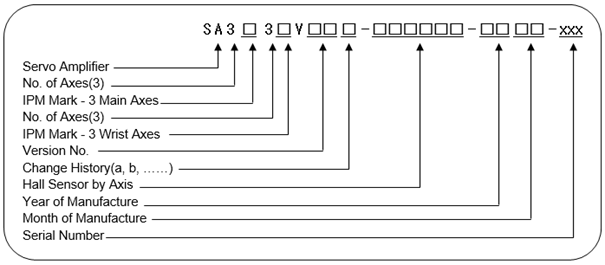
Table 4‑35 The Mark of Type of Servo Driver Series
Classification | Mark of Type |
Servo Amp | SA |
Table 4‑36 The Specifications of Drive Unit
Item | Classification | Application | ||
IPM Capa. | 1L | 4X | HC2500BD-10 | 6 Axis All-In-One Type |
3X | 3Y | HS165 applied | ||
3X | 3Z | HC2500BD-00, HC2500IK | ||
Year | 00 ~ 99 | Year of Manufacture: 2000 ~ 2099 | ||
Month | 01 ~ 12 | Month of Manufacture: 1 ~ 12 | ||
Serial No. | 001 ~ 999 | No. of units manufactured per month: 1 ~ 999 | ||
Table 4‑37 IPM Capacity
Large/Medium Size | L | (IPM Rated Current) 150A, (Hall Sensor Rated Current) 4V/75A |
X | (IPM Rated Current) 100A, (Hall Sensor Rated Current) 4V/50A | |
Y | (IPM Rated Current) 75A, (Hall Sensor Rated Current) 4V/50A | |
Z | (IPM Rated Current) 50A, (Hall Sensor Rated Current) 4V/25A |
Table 4‑38 Hall Sensor Marks
AMP Model | Hall Sensor Mark (Spec.) | Full-Scale Current (Im) | AMP Feedback Constant (Iv) |
Large/Medium –Scale (6 Axis) Amp | 0 (4V/75A) | 140.62Apeak | PM150CSD060(150A) |
1 (4V/50A) | 93.75Apeak | PM150CSD060(150A) PM100CSD060(100A) PM75CSD060(75A) PM50CSD060(50A) | |
2 (4V/25A) | 46.87Apeak | ||
3 (4V/15A) | 28.12Apeak | ||
4 (4V/10A) | 18.75Apeak | ||
5 (4V/ 5A) | 9.37Apeak |
| Caution: As the drive unit varies depending on the robot, so please check out the form of it in replacing it. |


Figure 4.49 BD552 Component Layout
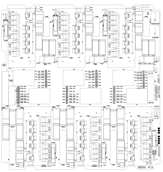
Figure 4.50 BD551 Component Layout
Table 4‑39 BD552 Connector
Name | Use | External Device Connection |
CNBS1, 2, 3 | PWM Signal and Error Signal | Servo Board(BD542) CNBS1,2,3 |
CNSGA | /PWMON, SVERR, BRAKE | Sequence Board (BD530) CNSGA |
CNPWM 1~6 | PWM Signal and Error Signal | Servo Amp BD551 CNPWM1~6 |
CNPWM 7~8 | Additional Axis PWM Signal and Error Signal | Option Board(BD554, BD556) CNPWM |
Table 4‑40 BD551 Connector
Name | Use | External Device Connection |
CNDBPOW | Power for DB control | CNPB of BD5C0 |
CNDB7, 8 | Additional Axis DB drive signal | Option board (BD554, BD555) CNDB |
CNM 1~6 | Motor Connection | CMC1, CMC2 |
CNPWM 1~6 | PWM signal and error signal | Servo Amp BD552 CNPWM1~6 |
CNPPNN | Power for motor drive | Drive Power Unit (BD561) CNPN1 |
CNFG1 | The frame ground of the Main axis motor | CMC1 |
CNFG2 | The frame ground of the Wrist Axis motor | CMC2 |
Table 4‑41 BD552 LEDs
Name | Color | Status Display |
SV | Yellow | ON if PWM is ON |
POW | Green | OFF if current dip/sag occurs |