4.2. The Arrangement of Parts
4.2. The Arrangement of Parts
Table 4-1 shows the main parts of Hi5-N00 controller and the name of each part, and Figure 4.5, 4.6 and 4.7 show the arrangement of them.
Table 4‑1 The Name of Each Part of Hi5-N00 Controller
No. | Type | Item |
1 | RACK | Rack |
2 | BD501 | Backplane Board |
3 | SR1 | DC Multi Power Unit(SMPS: HDI-200) |
4 | BD510 | Main Board |
5 | BD542 | Servo Board |
6 | BD530/531 | System Board |
7 | PDM30 | Electrical Module |
8 | SD1L2C | Middle-Size Diode Module |
9 | SA3X3Y | Middle-Size 6-Axis Servo Drive Unit (Standard Specifications) |
9-1 | SA3A3D | Small-Size 6-Axis Servo Drive Unit (Standard Specifications, Including a DIOD module) |
10 | SA1X1X | Middle-Size 2-Axis Servo Drive Unit (Option) |
10-1 | SA1X1A | Middle-Size 1-Axis, Small-Size 1-Axis Servo Drive Unit (Option) |
10-2 | SA1A1A | Small-Size 2-Axis Servo Drive Unit (Option) |
11 | EM. SW | Emergency stop switch |
12 | BD5B1 | Small Door Board |
13 | NFB | No Fuse Breaker |
14 | FAN1 | Rack radiating fan |
15 | FAN2 | Lower fan for upper circulation |
16~17 | FAN3~5 | Servo-drive unit radiating fan |
18 | NFT1 | Line Noise Filter |
19~20 | DR1~2 | Regeneration discharge resistance |
21 | TR1 | Transformer |
22 | CMC1 | Power Cable Lead-In Connector for Motor Drive 1 |
23 | CMC1 | Power Cable Lead-In Connector for Motor Drive 2 |
24 | CEC1 | Motor Encoder Communications Cable Lead-In Connector |
25 | CNRTP | Teach pendant Cable Lead-In Connector |
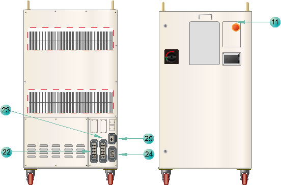
Figure 4.5 Hi5-N00 Part arrangement parts in the exterior of a controller
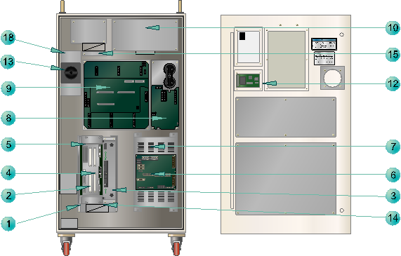
Figure 4.6 Part arrangement in the interior of the front surface of the Hi5-N00 controller
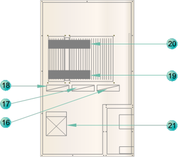
Figure 4.7 Part arrangement in the interior of the rear surface of the Hi5-N00 controller
Table 4-2 shows the main parts of Hi5-C10 controller and the name of each part, and Figure 4.8, 4.9 and 4.10 show the arrangement of them.
Table 4‑2 The Name of Each Part of Hi5-C10 Controller
No. | Type | Item |
1 | RACK | Rack |
2 | BD501 | Backplane Board |
3 | SR1 | DC Multi Power Unit(SMPS: HDI-200) |
4 | BD510 | Main Board |
5 | BD542 | Servo Board |
6 | BD530/531 | System Board |
7 | PDM30 | Electrical Module |
8 | SD1L2C | Middle-Size Diode Module |
9 | SA3X3Y | Middle-Size 6-Axis Servo Drive Unit (Standard Specifications) |
9-1 | SA1L5X | Servo-drive apparatus for HC2500B2D-XXXX-10 (optional specifications) |
9-2,3 | SA3X3Z | Servo-drive apparatus for HC2500B2D-XXXX-00 (optional specifications) Servo-drive apparatus for HC2500B1D-XXXX-10 (optional specifications) |
10 | BD58A | LDIO board |
11 | BD58B | Safety relay board |
12 | BD5B1 | Small Door Board |
13 | EM. SW | Emergency stop switch |
14 | SR2 | DC power apparatus for a sensor |
15 | SR3 | Elevation shaft fall prevention brake and DC power apparatus for a robot fan |
16 | NFB1 | Breaker of driving device wiring (No Fuse Breaker) |
17 | NFB2 | Breaker for control power wiring (No Fuse Breaker) |
18 | TBMAIN1 | Terminal Block for inputting driving device power (Terminal Block) |
19 | TBMAIN2 | Terminal Block for inputting control power (Terminal Block) |
20 | TBPW1 | Terminal Block for interior power (Terminal Block) |
21 | FAN1 | Rack radiating fan |
22~24 | FAN2~4 | Servo-drive unit radiating fan |
25 | TR1 | Transformer |
26 | NFT1 | Line Noise Filter |
27~28 | DR1~2 | Regeneration discharge resistance |
29 | CMC1 | Power Cable Lead-In Connector for Motor Drive 1 |
30 | CMC2 | Power Cable Lead-In Connector for Motor Drive 2 |
31 | CEC1 | Motor Encoder Communications Cable Lead-In Connector |
32 | CNRTP | Teach pendant Cable Lead-In Connector |
33 | CIOC1 | Sensor cable inserted in the connector |
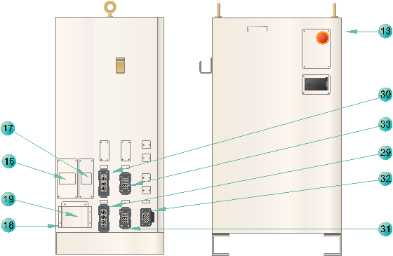
Figure 4.8 Hi5-C10 Part arrangement parts in the exterior of the controller
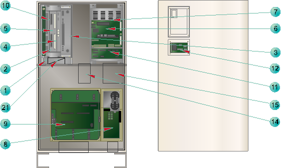
Figure 4.9 Part arrangement in the interior of the front surface of the Hi5-C10 controller
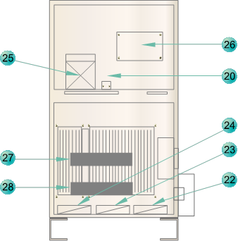
Figure 4.10 Part arrangement in the interior of the rear surface of the Hi5-C10 controller
Table 4-3 shows the main parts of Hi5-C20 controller and the name of each part, and Figure 4.11, 4.12 and 4.13 show the arrangement of them.
Table 4‑3 The Name of Each Part of Hi5-C20 Controller
No. | Type | Item |
1 | RACK | Rack |
2 | BD501 | Backplane Board |
3 | SR1 | DC Multi Power Unit (SMPS: HDI-200) |
4 | BD510 | Main Board |
5 | BD542 | Servo Board |
6 | BD530/531 | System Board |
7 | PDM30 | Electrical Module |
8 | SD1L2C | Middle-Size Diode Module |
9 | SA3X3Y | Middle-Size 6-Axis Servo Drive Unit (Standard Specifications) |
9-1 | SA4X2Z | Servo-drive apparatus for HC2500IK-L0(optional specifications) Servo-drive apparatus for HC2500IK-R0 (optional specifications) |
10 | BD580 | DIO board |
11 | BD570 | CC-link board |
12 | BD5B1 | Small Door Board |
13 | EM. SW | Emergency stop switch |
14 | SR2 | DC power apparatus for a sensor |
15 | SR3 | Elevation shaft fall prevention brake and DC power apparatus for a robot fan |
16 | NFB1 | Breaker of driving device wiring (No Fuse Breaker) |
17 | NFB2 | Breaker for control power wiring (No Fuse Breaker) |
18 | TBMAIN1 | Terminal Block for inputting driving device power |
19 | TBMAIN2 | Terminal Block for inputting control power (Terminal Block) |
20 | TBPW1 | Terminal Block for interior power (Terminal Block) |
21 | FAN1 | Rack radiating fan |
22~24 | FAN2~4 | Servo-drive unit radiating fan |
25 | FAN5 | Fan for front surface radiation |
26 | TR1 | Transformer |
27 | NFT1 | Line Noise Filter |
28~29 | DR1~2 | Regeneration discharge resistance |
30 | CMC1 | Power Cable Lead-In Connector for Motor Drive 1 |
31 | CMC2 | Power Cable Lead-In Connector for Motor Drive 2 |
32 | CEC1 | Motor Encoder Communications Cable Lead-In Connector |
33 | CNRTP | Teach pendant Cable Lead-In Connector |
34 | CIOC1 | Sensor cable inserted in the connector 1 |
35 | AMC1 | Insertion connector 1 for the power cable to drive a motor in an additional axis |
36 | AEC1 | Insertion connector 1 for the communication cable of a motor encoder in an additional axis |
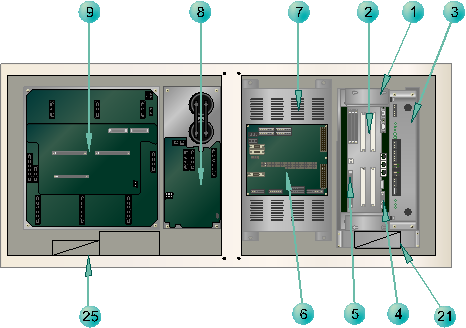
Figure 4.11 Part arrangement in the interior of the left side of the Hi5-C20 controller
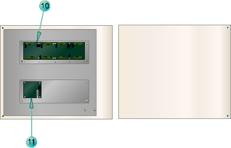
Figure 4.12 Part arrangement in the left side door of the Hi5-C20 controller
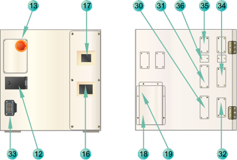
Figure 4.13 Part arrangement in the front and rear surfaces of the Hi5-C20 controller
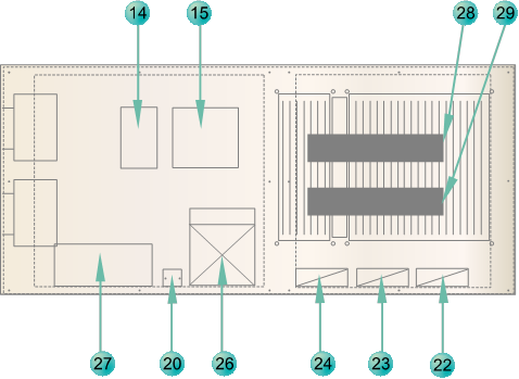
Figure 4.14 Part arrangement in the interior of the right side of the Hi5-C20 controller