3.6.2. Permitted inertia moment estimation
3.6.2. Permitted inertia moment estimation
Loads must be kept below maximum conditions shown in [Figure 3.8] ~ [Figure 3.11].
n Step 1
Calculate the inertia moment value of the load at each wrist axis center (Ja4, Ja5, Ja6)
Ja4- Inertia moment from R2 axis rotation center
Ja5- Inertia moment from B axis rotation center
Ja6- Inertia moment from R1 axis rotation center
n Step 2
Check if the inertia moment is under the thread according to the permissible inertia moment table.
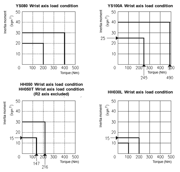
Figure 3.12 Wrist Axis Load Condition: [YS080/YS100A/HH050/HH030L/HH050T]
 Allowable Moment of Inertia
Table 3‑3 Allowable Moment of Inertia
Robot Model | Allowable Moment of Inertia | ||
R2 Axis Rotation | B Axis Rotation | R1 Axis Rotation | |
YS080 | 30 kg·m²(3.06 kgf·m·s²) | 20 kg·m²(2.04 kgf·m·s²) | |
YS100A | 40 kg·m²(4.08 kgf·m·s²) | 25 kg·m²(2.55 kgf·m·s²) | |
HH050 | 30 kg·m²(2.04 kgf·m·s²) | 15 kg·m²(1.53 kgf·m·s²) | |
HH030L | 15 kg·m²(1.53 kgf·m·s²) | 10 kg·m²(1.02 kgf·m·s²) | |
HH050T | - | 30 kg·m²(2.04 kgf·m·s²) | 15 kg·m²(1.53 kgf·m·s²) |