6.4.2. How to Replace the Motor
6.4.2. How to Replace the Motor
| Caution
This robot has a brake built into the motor to maintain the posture of the arm, so the arm will fall if the motor is removed. You must take safety measures such as hanging the arm using a crane and inserting fixing bolts to fix the first and second arms to prevent the falling. |

(1) Set the controller to the teaching mode and set the Operation Ready function to the [ON] state. If it is impossible to set the Operation Ready function to the [ON] state, you should make sure that the arm does not fall and that the arm is sufficiently fixed. After that, you can perform the work starting from step (4.)
(2) Put the axis that requires the replacement of the motor into the basic posture.
(3) For the main axes (S, H, V): Refer to [Figures 6.1–6.4.]
For H and V axes, insert the fixing bolts to prevent the arm from falling.
For the wrist axes (R2, B, and R1): Set the origin of each axis by using the scale.
(4) Turn [OFF] the power of the controller and then turn [OFF] the primary power.
(5) Separate the motor wirings.
(6) Separate the motor from the manipulator by removing the motor attachment bolts.
When removing the motors of H and V axes, you should make sure that the lip of the oil seal is not damaged by the gear attached on the axis of the motor.
(7) Separate the gear attached on the axis of the motor.
At this time, take precautions not to allow a strong impact to be applied to the axis of the motor.
(8) Apply a thin layer of grease to the axis of the motor to be assembled and assemble the gear.
At this time, the bolts to be used to fasten the gear to the axis of the motor should be cleaned and degreased and applied with anti-loosening bond (Loctite 243) to the screw and then tightened with the prescribed torque using a torque wrench. In addition, the bolts should be slowly tightened in the symmetrical order.
(9) Apply a small amount of grease to the lip of the oil seal and an appropriate amount of grease to the tooth surface of the gear, and then assemble the motor to the manipulator. When attaching the motors of the main axes, you should make sure that the lip of the oil seal is not damaged by the gear attached to the axis of the motor.
(10) Connect the wiring of the motor.
(11) When the motors of the H and V axes are replaced, replenish new grease as much as the amount of leaked grease.
(12) Reset the encoder of the axis for which the motor has been replaced.
 Cautions
Before calibrating the encoder, you should set the Operation Ready function to the [ON] state, and then press the Enable switch of the teach pendant for 2–3 seconds to check if the power is turned on.
(13) Calibrate the encoder of the axis for which the motor has been replaced by referring to the [Calibrating the Encoder] section in the Controller Operation Manual.
(14) Disassemble the M20 bolts, which are designed for preventing the arms of H and V axes from falling.
(15) Check whether there is any abnormality.


Figure 6.1 Position for Inserting the Fixing Bolt for the Primary Arm (H Axis)
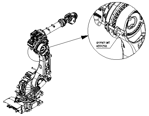
Figure 6.2 Position for Inserting the Fixing Bolt for the Secondary Arm (V Axis)

Figure 6.3 S-Axis Motor Assembly

Figure 6.4 H-Axis and V-Axis Motor Assemblies
| Caution
When the V-axis motor is being replaced, if the entire upper arm is not accurately attached to the mechanical stopper in the direction of gravity, the upper arm may rotate while the motor is being separated. |

Figure 6.5 Wrist-Axis Motor Assembly