3.6.3. Examples of Calculation of the Allowable Torque and Allowable Moment of Inertia (HS180)
3.6.3. Examples of Calculation of the Allowable Torque and Allowable Moment of Inertia (HS180)
(1) Case #1 Simple two-dimensional model
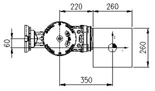
Figure 3.11Two-Dimensional Load Model
M – Load weight
Jxx - Moment of inertia in the direction of the X axis at the center of the gravity of the load
Jyy - Moment of inertia in the direction of the Y axis at the center of the gravity of the load
Jzz - Moment of inertia in the direction of the Z axis at the center of the gravity of the load
Ja4 - Moment of inertia at the center of rotation of the R2 axis
Ja5 - Moment of inertia at the center of rotation of the B axis
Ja6 - Moment of inertia at the center of rotation of the R1 axis
☞ Load condition: Stainless Steel (with mass of 138.15 kg) with a width of 260 mm and a thickness of 260 mm
① Weight limit
Load weight: 
② Limit of the allowable torque
The position of the center of gravity with respect to B axis: LX = 350 mm, LY = 0 mm and LZ = -60 mm
Each distance from B axis and R1 axis to the center of gravity can be calculated respectively as follows.
Distance with respect to the B axis
Distance with respect to the R1 axis
Load torque of the B axis
Load torque of the R1 axis
③ Limit of the allowable moment of inertia
The moments of inertia of the load at the center of gravity: Jxx= 1.56kgm2, Jyy= 1.56 kgm2, and Jzz= 1.56 kgm2
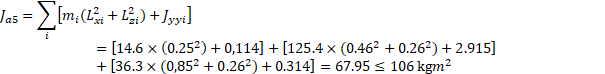
Moment of inertia of the B axis (Ja5)

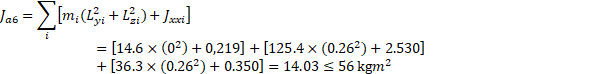
Moment of inertia of the R1 axis (Ja6)

④ Conclusion
It is safe because all conditions of weight, torque, and moment of inertia satisfy the conditions of limit.
(2) Case #2 Complex three-dimensional model

Figure 3.12Two-Dimensional Shape of a Three-Dimensional Load Model
Combination of aluminum block shapes
(σ=0.0027 g/mm3: 176.3 kg)
m1 (60×300×300) 14.6kg
m2 (480×440×220) 125.4kg
m3 (280×300×160) 36.3kg
mi - Load weight of i block
LXi - Position of the center of gravity of i block in the direction of X axis
LYi - Position of the center of gravity of i block in the direction of Y axis
LZi - Position of the center of gravity of i block in the direction of Z axis
① Weight limit
Load weight: 
② Limit of the allowable torque
The position of the center of gravity of all loads at the center of rotation of the B axis can be calculated as follows.

 (Y축 대칭이므로)

Position of the center of gravity of all blocks with respect to B axis  = 520.85mm,
  = 0mm,
  = -238.47mm
Distance from the B axis to the center of gravity
Distance from the R1 axis to the center of gravity
Load torque of the B axis
Load torque of the R1 axis
x1 y1 z1 – Lengths of m1 block in the x, y, and z directions respectively
x2 y2 z2 – Lengths of m2 block in the x, y, and z directions respectively
x3 y3 z3 – Lengths of m3 block in the x, y, and z directions respectively
LX1, LY1, LZ1 - Position of the center of gravity of m1 block at the center of rotation of the B axis
LX2, LY2, LZ2 - Position of the center of gravity of m2 block at the center of rotation of the B axis
LX3, LY3, LZ3 - Position of the center of gravity of m3 block at the center of rotation of the B axis
Jxx1, Jyy1, Jzz1 – Moment of inertia of each of x, y, and z axes at the center of gravity of m1 block.
Jxx2, Jyy2, Jzz2 – Moment of inertia of each of x, y, and z axes at the center of gravity of m2 block.
Jxx3, Jyy3, Jzz3 – Moment of inertia of each of x, y, and z axes at the center of gravity of m3 block.
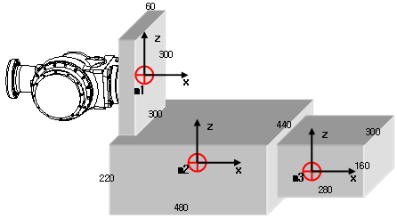
Figure 3.13Three-Dimensional Shape of a Three-Dimensional Load Model
③ Limit of the allowable moment of inertia
Table 3‑3 Moment of Inertia at the Center of Gravity of Each Block
Block weight (kg) | Center of gravity (LX, LY, LZ) | Jxx | Jyy | Jzz |
m1 (14.6) | (0.25, 0, 0) | 0.219 kgm2 | 0.114 kgm2 | 0.114 kgm2 |
m2 (125.4) | (0.48, 0, -0.26) | 2.530 kgm2 | 2.915 kgm2 | 4.433 kgm2 |
m3 (36.3) | (0.89, 0, -0.26) | 0.350 kgm2 | 0.314 kgm2 | 0.509 kgm2 |
Moment of inertia of the B axis (Ja5)
Moment of inertia of the R1 axis (Ja6)
④ Conclusion
It is safe because all conditions of weight, torque, and moment of inertia satisfy the conditions of limit.