3.6.1. Calculating the Allowable Load Torque
3.6.1. Calculating the Allowable Load Torque
The load to be attached to the tip of the wrist axis of the robot is regulated by the allowable weight, allowable load torque, and allowable moment of inertia. The direction of the coordinate system to be used for calculating the load torque and moment of inertia is the same as that of the robot base coordinate system. The review of the R2 axis will be performed in the same way as done for the B axis.
n Step 1
Calculate the position of the center of gravity at the center of rotation of the B axis (LX, LY, LZ.)
Lx: Position of the center of gravity in the direction of X axis
Ly: Position of the center of gravity in the direction of Y axis
Lz: Position of the center of gravity in the direction of Z axis
n Step 2
Calculate the distance from the B and R1 axes to the center of gravity respectively.
 ,
, 
LB: Distance from the center of rotation of B axis to the center of gravity
LR1: Distance from the center of rotation of the R1 axis to the center of gravity
n Step 3
Calculate the load torque based on the calculated distance.


 : Load torque at the center of rotation of B axis
 : Load torque at the center of rotation of the R1 axis
 : Load mass
 : Gravitational acceleration
n Step 4
Check whether the load torque calculated in Step 3 is below the limit value based on the table of allowable load torques.
n Note: If the load mass is similar to the mass indicated on the torque curve below, the verification of the load torque can be substituted by checking whether the distance calculated in Step 2 is distributed within the torque curve instead of going through Steps 3 and 4. If the calculated distance is within the torque curve, the calculated load torque is smaller than the allowable load torque, and if it is located outside the torque curve, the calculated load torque is larger than the allowable load torque.
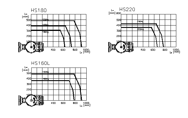
Figure 3.10 Wrist Axis Torque Curve
 Allowable Load Torque
Table 3‑1Allowable Load Torque
Payload | Allowable Load Torque | ||
Rotation of the R2 axis | Rotation of the B axis | Rotation of the R1 axis | |
HS160L,HS180 | Within 1079 N·m (110 kgf·m) | Within 566 N·m (58 kgf·m) | |
HS220 | Within 1422 N·m (145kgf·m) | Within 770 N·m (79 kgf·m) | |