3.6.1. Permitted load torque estimation
3.6.1. Permitted load torque estimation
The load, which will be applied to the mechanical interface of robot's wrist axis, is restricted by allowable weight, allowable load torque and allowable moment of inertia.
 Allow payload weight :
Table 3‑1 Allow payload weight
Robot model | Allow payload weight |
HS165DC | 1,619N (165kgf) or less |
 allowable load torque
Table 3‑2 Allowable Load Torque
Robot model | allowable load torque | ||
J3-axis rotation | J4-axis rotation | J5-axis rotation | |
HS165DC | 980N·m(100kgf·m) or less | 490 N·m (50 kgf·m) or less | |
 allowable moment of inertia
Table 3‑3 allowable moment of inertia
Robot model | allowable moment of inertia | ||
J3-axis rotation | J4-axis rotation | J5-axis rotation | |
HS165DC | 64.68kg·m²(6.6kgf·m·s²) | 17.64kg·m²(1.8kgf·m·s²) | |
Loads must be kept below maximum conditions shown in [Figure 3.6].
[Figure 3.6] indicates the range in which the material point can be located when the applied load is at the material point. However, as it is hardly the case where the actual load (end effector) is at the material point, assess by calculating the inertia moment of each axis. To give an example of the applied load is assumed to be at the material point:,
(Example) When the robot type is HS165DC, and the weight of the applied load is 165 kg
■The allowable center location from the center of the J5 axis
① The allowable central location in terms of allowable torque
LR1 ≤(allowable torque) / (load weight)
LR1 = 490 Nm / (165 kg ×9.8 m/s2) = 0.30 m
② The allowable central location in terms of allowable inertia moment
LR1 ≤(allowable inertia moment/load weight)1/2
= (17.64 kg·m2/165 kg)1/2 = 0.33 m (> 0.30 m)
From the above results, the distance from the center of the J5 axis will be regulated by the allowable torque and be within 0.30 m.
■The allowable central location from the center of the J4 axis
① The allowable central location in terms of allowable torque
LB ≤(allowable torque) / (load weight)
LB = 980 Nm / (165 kg ×9.8 m/s2) = 0.61 m
② The allowable central location in terms of allowable inertia moment
LB ≤(allowable inertia moment / load weight)1/2
= (64.68 kg·m2 / 165 kg )1/2 = 0.63 m (> 0.61 m)
From the above results, the distance from the center of the J4 axis will be regulated by the allowable torque and be within 0.61 m.
n Torque Map
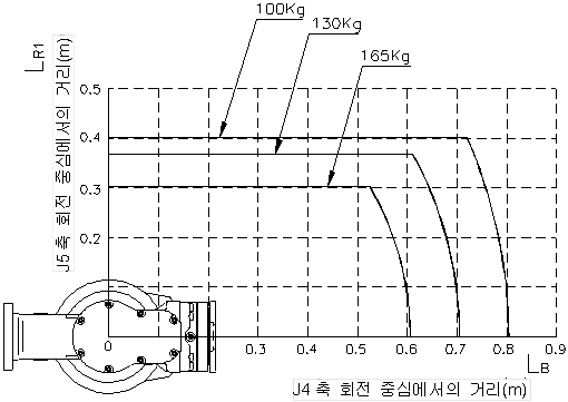
Figure 3.6 Wrist Axis Torque Mapping