6.4.2. How to Replace Motor
6.4.2. How to Replace Motor
(1) Set the controller to teaching mode and set the robot to standby [ON] condition. If the robot is not in standby [ON] condition, check whether the arm is sufficiently fixated to avoid it from dropping. And then proceed to (4).
(2) For H,V axis: Refer to [Fig. 6.2]
To prevent the arm from falling, insert the fixating pin or bolt.
(3) For wrist axis (R2, B, and R1): Set the zero point for each axis by using the scale or groove.
(4) Turn the main power [OFF] with the controller power [OFF].
(5) Disconnect the connector from the motor.
(6) Remove attachment bolts of motor and pull the motor out of robot. When removing motors of axis H or V, be sure not to damage the lip of oil seal due to the gear attached to the axis of motor.
(7) Detach the gear from the motor shaft. Be careful to avoid excessive impact to the motor.
(8) Assemble the gear after lightly applying grease to the shaft.
The bolt used to attach the gear to the shaft should be cleaned and removed of grease before using. Apply Loctite 243 to the screw part of the bolt, and then tighten it using a torque wrench in a regular torque. Besides, slowly tighten the bolt in a symmetrical order.
(9) Assemble the motor on the robot after applying a small amount of grease to the lip of oil seal
and applying a moderate amount of grease to the teeth of gear. When assembly the main
axis motor, be sure not to damage the lip of oil seal.
(10) Connect the connector to the motor.
(11) After you have replaced the H and V axis motor, newly refill the grease.
(12) Reset the encoder of the axis whose motor is replaced.
 Warning
Before encoder correction, check motor connections, with motors [ON], while pressing the Enable switch for 2~3 seconds.
(13) Perform the encoder calibration about the axis whose motor is replaced. Refer to the chapter [Encoder Calibration] in the controller operating manual.
(14) Disassemble the pin or bolt to prevent the H and V axis arm from falling.
(15) Confirm that there is no error in robot's motion.
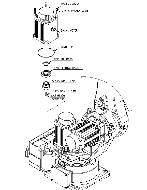
Figure 6.1 S axis motor disassembly diagram

Figure 6.2 Robot position when replacing the H/V axis motor

Figure 6.3 H axis motor replacement
| Caution
When replacing the V axis motor, the upper arm must accurately be aligned to the direction of gravity to the mechanical stopper so that the upper arm does not rotate. |

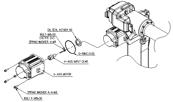
Figure 6.4 V-axis Motor
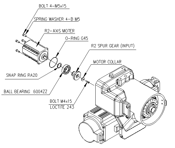
Figure 6.5 R2-axis Motor (HH020/HH010L)

Figure 6.6 B-axis Motor

Figure 6.7 R1-axis Motor