3.1. Setting of the CC-Link IE Slave
3.1. Setting of the CC-Link IE Slave
Set the node number and network number to use the CC-Link IE Field Slave. Carry out the setting according to the following procedures.
(1) Select『[F2]: System』 → 『2: Control Parameters』 → 『2: Input and Output Signal Setting』 → 『16: CC-Link IE Slave Setting and Diagnosis』.
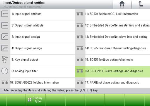
Figure 3.1 CC-Link IE Slave Setting and Diagnosis Menu
(2) In the CC-Link IE Slave Setting and Diagnosis screen, set the items such as input in case of an error, node number, network number and input and output data mapping, and then click Apply button.
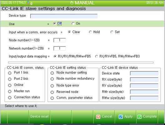
Figure 3.2 CC-Link IE Field Slave Setting Screen
n Whether to use:
Set this option to On to use CC-Link IE Field slave communication.
n Input in case of communication error:
This option is to process the input data (FB5.X or FB3.X) when an error occurs to CC-Link IE Field slave communication. If it is set to Clear, all input data will be cleared to 0 when a communication error occurs. If it is set to Hold, the last valid value will be maintained when a communication error occurs. When it is set to Set, all input signals will be set to 1 when a communication error occurs.
n Node number:
The valid range of the CC-Link IE Field slave node numbers is 1 ~ 120. It is required to set the number in a way that it can match the settings of the master.
This setting will be valid only when all DIP switch pins #1 ~ #7 of the CC-Link IE communication board are ON. If the DIP switch pins #1 ~ #7 of the communication board are set within the range of 1 ~ 120, the value will become node number.
n Network number:
The valid range for the CC-Link IE Field slave network number is 1 ~ 239. Set it in a way that it can match the setting of the master.
n Input and output data mapping:
Set which object of the Hi5a controller will be mapped to the RX / RY / RWr / RWw of CC-Link IE Field Master.
Table 3‑1 I/O Mapping
CC-Link IE master | Input and output data mapping | |
|
| |
RX | FB5.Y1~512 FB5.YB1~64 FB5.YW1~32 FB5.YL1~16 FB5.YF1~16 | FB5.Y1~960 FB5.YB1~120 FB5.YW1~60 FB5.YL1~30 FB5.YF1~30 |
RX | FB5.X1~512 FB5.XB1~64 FB5.XW1~32 FB5.XL1~16 FB5.XF1~16 | FB5.X1~960 FB5.XB1~120 FB5.XW1~60 FB5.XL1~30 FB5.XF1~30 |
RWr | FB5.Y513~960 FB5.YB65~120 FB5.YW33~60 FB5.YL17~30 FB5.YF17~30 | FB3.Y1~960 FB3.YB1~120 FB3.YW1~60 FB3.YL1~30 FB3.YF1~30 |
RWw | FB5.X513~960 FB5.XB65~120 FB5.XW33~60 FB5.XL17~30 FB5.XF17~30 | FB3.X1~960 FB3.XB1~120 FB3.XW1~60 FB3.XL1~30 FB3.XF1~30 |


| After changing the settings, you must click the 『[F6]: Apply』 button to reflect and store the settings in the controller. If you change the settings while the ‘Whether to use’ option is set the On state, the change will be reflected after the system or the controller is rebooted. |
