6.1. Embedded DeviceNet Master Connection Node State
6.1. Embedded DeviceNet Master Connection Node State
The communication state of the slave nodes connected to the embedded DeviceNet master can be checked.
(1) Select the item. “[F1]: Service” → “1: Monitoring” → “15: Embedded fieldbus node state”
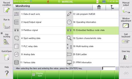
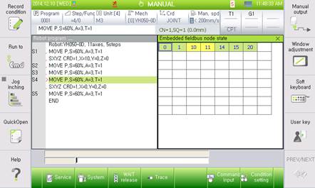
Figure 6.1 DeviceNet diagnosis
(2) The node number of the embedded DeviceNet master (MAC ID) is 0.
Select the embedded DeviceNet master, and press the [Enter] button to enter the screen of the embedded DeviceNet master setting.
The node state in the embedded fieldbus will be displayed as green when it is normal. However, the DeviceNet master stops because the embedded PLC stops, then it will be displayed as IDLE.
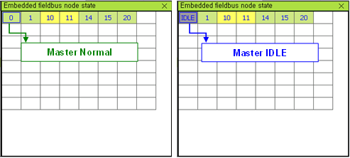
Figure 6.2 DeviceNet master state
(3) The communication state of the slaves connected to the embedded DeviceNet master will be displayed in the node number by each slave.
Green and yellow are normal communication nodes, and red is the node with communication error.
(Green is the slave product of CREVIS, and other products will be displayed as yellow.)
Select the node with communication error, and then enter the [Enter] button to display error information.
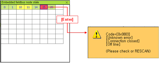
Figure 6.3 Slave State Information
(4) Select the slave node number, and press the [Enter] button to enter the IO monitoring screen of the corresponding node.
On the other hand, press the “[F1]: Node status” on the IO monitoring screen to go to the node state diagnosis screen.
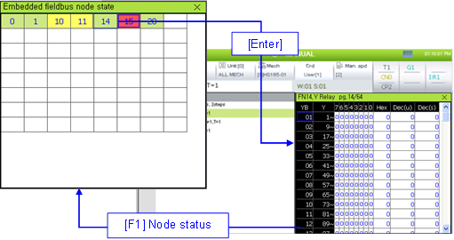
Figure 6.4 I/O monitoring screen change