2.3. Weaving and Arc sensing condition setting
2.3. Weaving and Arc sensing condition setting
(1) Weaving condition
Because arc sensing basically includes the weaving, it is included in the weaving condition file. The weaving condition file is displayed in the following screen when you locate the cursor on the {WEAVON WEV#=?} command and press the [QuickOpen] key.
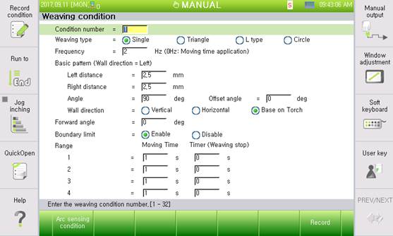
Figure2.2 Weaving condition setting
l Condition number: [1] (Range: 1–32)
The weaving condition number is currently under editing.
l Weaving type: <Simple harmonic motion, triangle, L type, and circular>
Designate the type of weaving.
l Frequency: [2] In Hertz (Range: 0.0–10.0)
Set the weaving frequency. The range is 0.0–10.0 Hz. If the frequency is set to “0,” apply the moving time.
l Basic pattern
Set the pattern of weaving.
- Wall direction distance: [2.5] (Range: 0.5–50.0 mm)
Left leg length viewed from the weaving proceeding direction
- Opposite direction distance: [2.5] (Range: 0.5–50.0 mm)
Right leg length viewed from the weaving proceeding direction
- Angle: [90°] (Range: 0.1°–180.0°)
Designate the angles of the wall and opposite-direction weaving surfaces.
- Wall direction: <Vertical direction, horizontal direction, and torch standard>
Designate what reference is to be used to set the direction of the wall. The default is the “Torch posture as reference.”
- Offset angle: [0°] (Range: −90.0° to 90.0°)
If the wall direction is based on the “Torch standard,” designate the angle to shift in the middle of the weaving surface.
l Forward angle: [0°] (Range: −90.0° to 90.0°)
Weaving angle direction for the proceeding direction. If it is “0,” the forward and weaving directions are perpendicular. Set the angle of inclination if diagonal weaving is needed.
l Boundary limit: <Enable, Disable>
Set if the weaving trajectory is limited by the boundary of the welding start and endpoints. If it is enabled, the weaving trajectory is limited within the welding section.
l Moving Time: [1] (Range: 0.01–10.0 s); Timer: [0] (Range: 0.00–2.00)
If the weaving frequency is set to “0,” weaving is performed with the moving time. Set the moving time for sections and the weaving stop time between them.
(2) Arc Sensing Condition - User
After “[F1]: Arc sensing condition” in the weaving condition dialog box is pressed, the following “Arc sensing condition – User”dialog box is displayed.
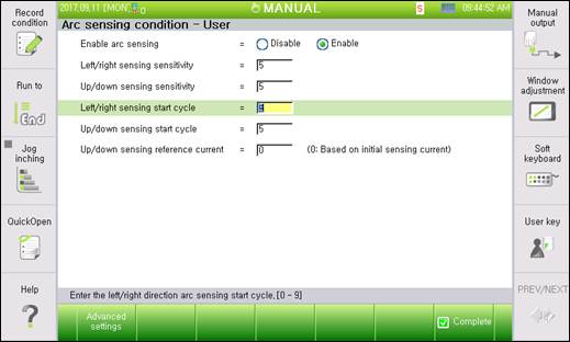
Figure2.3 Arc sensing condition – User setting
l Enable arc sensing: <Enable, Disable>
Set to enable or disable arc sensing.
l Left/right side sensing sensitivity: [0–10]
Set the left/right sensing sensitivity on the weaving surface. If it is set to “10,” it follows the entire maximum correction distance per second set by the engineer. If it is set to “0,” it is not followed to the left/right side.
l Up/down sensing sensitivity: [0–10]
Set the up/down sensing sensitivity on the weaving surface. If it is set to “10,” it follows the entire maximum correction distance per second set by the engineer. If it is set to “0,” it is not followed to the up/down side.
l Left/Right side sensing start cycle: [0~9]
Set the weaving cycle to start tracking with the left/right side sensing. It is desirable to skip two to three cycles as the welding current is unstable upon starting arc welding.
l Height sensing start cycle: [4~10]
Set the weaving cycle to start tracking with the up/down sensing. Set the cycle after starting the left/right side sensing as the reference current needs to be set for the up/down sensing.
l Up/down sensing reference current: [0–3,000] A
The reference current for up/down sensing: The current is decreased or increased if the projection of the wire is increased or decreased, respectively, for arc welding. Therefore, designate the reference current to adjust the torch height. If “0” is entered, select it based on the current value of the up/down sensing start cycle at the beginning of welding.
l Arc sensing type selection: <Welding line, Current difference, and Current difference + Gap>
Select the arch sensing following method.
Welding line: Performs the welding line tracking by taking as reference the position where the current is the lowest. This should be used for the root pass welding that has no sealing bead and tack welding.
Current difference: Performs the welding line following by comparing the current difference between both at the ends of the weaving. This can be used even when there is a root pass and a sealing bead. Basic option.
Current difference + Gap: This option makes it possible to adjust the weaving width and weaving speed, together with performing the welding line following, by using the current difference between both ends of the weaving. This is to be used for the butt welding in which there is deviation among workpieces.
(3) Arc Sensing Condition - Engineer
After the “[F1]: Advanced setting” in the “Arc sensing condition – User”dialog box is pressed, the following “Arc sensing condition – Engineer”dialog box is displayed.
※ Engineer privilege is required to enter this dialog box.
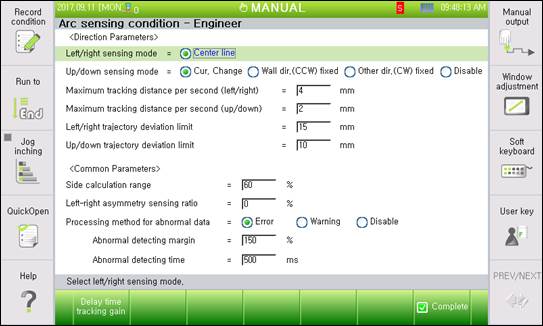
Figure2.4 Arc sensing condition –Engineer setting
l Left/right side sensing mode: <Center line>
Select the left/right side sensing mode. The center line mode is supported for now.
l Up/down sensing mode: <Current change, Wall direction fixation, Opposite direction fixation, and Disable>
An item to select the up/down method: General arc sensing can correct the height with the current change, so the current change is mostly used. However, aluminum welding may not correct the height with the current change, so the height can be sensed if one side is fixed with the wall or opposite-direction fixation.
If “Disable” is selected, only left/right side sensing is performed.
l Maximum correction distance per second (left/right): [0.1–20.0] mm
Set the left/right side maximum track distance per second. The actual maximum track distance is calculated as follows.
Actual maximum track distance (left/right) = Maximum correction distance per second (left/right) × left/right side sensing sensitivity / 10
l Maximum correction distance per second (up/down): [0.1–20.0] mm
Set the up/down maximum track distance per second. The actual maximum track distance is calculated as follows.
Actual maximum track distance (up/down) = Maximum correction distance per second (up/down) × up/down sensing sensitivity / 10
l Left/right trajectory escape limit: [0–200] mm
Maximum left/right side distance that the robot can track from the teaching trajectory. The robot will stop if it is out of the teaching trajectory beyond this value. If the robot is out of trajectory, this function may be used to minimize the distance to weld an incorrect position.
l Up/down trajectory escape limit: [0–200] mm
Maximum up/down distance that the robot can track from the teaching trajectory. The robot will stop if it is out of the teaching trajectory beyond this value. If the robot is out of trajectory, this function may be used to minimize the distance to weld an incorrect position.
l Side calculation range: [1–100]%
Set the current range to compare the left/right side current values. Perform the sensing with the current value from the left/right vertex of weaving by this range.
l Asymmetrical left/right side sensing rate: [−40 to 40]
Rate to track the welding line while forming the left/right side welding bead in an asymmetrical manner. Perform welding by shifting in the left (−) and right (+) directions within the entire weaving section according to the set rate.
This rate is proportional to the weaving width and will work correctly if the welding line track gain is correctly set.
If an excessive asymmetrical rate is set, the welding line may be avoided. In this case, reduce the asymmetrical rate.
l How to process abnormal data: <Error, warning, and disable>
This is the data processing method when the sensing input data is unstable during welding.
- Error: E32756 (The arc sensing current exceeded the normal range by the abnormality judgement time.) The error occurs, and the robot stops.
- Warning: W32756 (The arc sensing input data is unstable, so they exceeded the normal range by the abnormality judgement time.) The warning occurs, but the robot continues operation.
- Disable: It continues sensing by ignoring the abnormal data.
l Abnormality judgment margin: [100~200]%
This sets the margin to judge as abnormal current. Judgment of abnormal current is done based on the past 5 data points.
Upper limit of abnormal judgment = Average of past 5 data points × Abnormal judgment margin,
Lower limit of abnormal judgment = (Average of past 5 data points × 2 )–Upper limit of abnormal judgment
l Abnormality judgment time: [10~1000]m/sec
This sets the time to judge as abnormal when the input current exceeds the 『Abnormal judgment margin』. Although this value is an element used to decide how quickly the recognition of abnormal data can be judged, if this is set too low, a false error may be detected. Therefore, this must be set according to the environment.
l Trajectory deviation decrease: <Disable, Enable>
When the following based on the welding line is to be used and if the following direction calculated using the current difference between the left and right sides is different from the following direction calculated by considering the welding line, this menu makes it possible to select the handling method.
Disable: Reflects the welding-line–based compensation amount into the compensation distance
Enable: Handles the calculated compensation amount as 0 to maintain the existing compensation distance
l Maintaining the compensation distance during a step forward/backward: <Clear, Maintain>
If the step forward/backward operation is to be performed after stopping during arc sensing or during a multipass operation, this menu makes it possible to set whether to maintain the existing compensation distance.
Clear: Sets the compensation distance as 0
Maintain: Performs the step forward/backward operation while maintaining the compensation distance
(4) Data delay and following coefficient table
After the “[F1]: Delay time following coefficient” in the “Arc sensing condition – Enginer” dialog box is pressed, the following “Data delay and following coefficient table” dialog box is displayed.
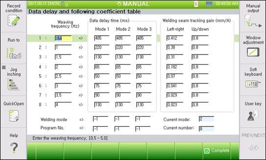
Figure2.5 Data delay and following coefficient table setting
l Weaving frequency
Enter the weaving frequency to enter the table data. In general, create the table from 0.5 to 4.0 Hz with an interval of 0.5 Hz.
l Data delay time
Enter the data delay time for each weaving frequency. This delay time is calculated through a separate test (refer to 6.2). Up to three modes can be entered by the welding mode (pulse and gas type) or the program number of the welding machine. The data delay time is applied during sensing according to the welding mode or the program number.
l Welding line following gain
Current value change gain according to torch position change for each weaving frequency: Left–right/up–down gains are separate and calculated through a separate test (refer to 6.2).
l Welding mode
Enter the mode of the welding condition to be used for sensing. Enter a value in the data delay time mode to apply by the referencing current mode displayed on the side after welding.
l Program number
Enter the program number of the welding machine to be used for sensing. Enter a value in the data delay time mode to apply by the referencing current number displayed on the side after welding.
※ If there is no mode that does not match with the welding mode or program number that is used for the current welding work, the delay time for the mode for which the welding mode is set as 0 and the program number set as 0 will be used as the default delay time. If the welder uses the job mode and many job numbers, sensing can be performed using this default delay time.