2.2. Input data setting for arc welding sensing
2.2. Input data setting for arc welding sensing
Analog and digital inputs as well aswelding data can be used to detect the arc welding current.
Each of them requires different settings.
(1) Select『[F2]: System』 →『4: Application parameter』 → 『2: Arc welding』 from manual mode.
(2) Item No. 13 of the arc application menu, the “Data input setting for sensing: [Enable, Disable]” can be set. With the “Valid” setting, press “[F1]: Input signal setting” to display the following screen, to set the input signals for arc welding sensing.
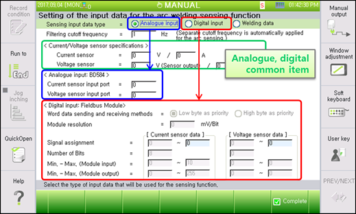
Figure2.1 Setting of the input data for arc welding sensing
(3) Select the type of sensing data to enable any item to set.
(4) With regard to sensor data filtering, it is required to set the filtering level that is to be applied to the input signal for arc sensing. When the welder sends a signal that is filtered for arc sensing, the sensing response speed will be made quicker if “No filter” or “Partial filtering” is set. If you are using a typical welder or current/voltage sensor, maximum filtering can be used..
(5) Current/voltage sensor specifications are common for analog and digital inputs. Set them according to the specifications of the sensor that will be used.
(6) If the analog voltage needs to be entered directly through the controller BD584 board, select "Analog input" and select the current/voltage sensor input port.
(7) If it is required to receive the analog voltage as a fieldbus signal using the fieldbus module for analog voltage input, select “Digital input.” Input data into the enabled items according to the module hardware specifications and communication node setting
(8) If a digital communication welding machine is used and the data refresh rate is fast, arc sensing can be performed with the data from the welding machine. In this case, select “Welding data.”