3.2.2. Robot–camera calibration
3.2.2. Robot–camera calibration
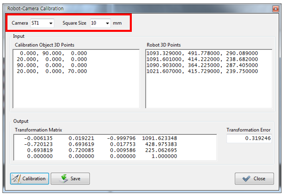
This is a process that matches the calibration plate coordinate system and the robot coordinate system.
When ST1 is selected in the camera combo box and the quadrangle size of the calibration plate is selected, the “Calibration Object 3D Points” will be generated automatically. Input four robot teaching points correspondingly, and then click the “Calibration” button. The relationship between the calibration plate coordinate system and the camera will then be displayed in the transformation matrix. At this time, the transformation error that is to be generated will be displayed through the “Transformation Error” item. If the error exceeds 1, check the robot teaching points again, and, if necessary, perform teaching again.
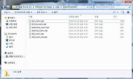
Clicking the “Save” button will store the transformation matrix information into the “C:*HRVision 3D-Stereo*Data*RobCalTransform” folder.