5.13.2.4. CAN Communication Connector CANS1, CANS2
5.13.2.4. CAN Communication Connector : CANS1, CANS2
When it comes to the CAN communication connector, two connectors of the identical pin specification, as shown below, are installed. This is because the cables are configured according to the Daisy Chaining method. Therefore, there will be no problem in the operation when connecting to any one of the two connectors.

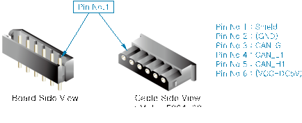
Figure 5.88 Method for the Connection of the CAN Connector of the Public 8-Point IO Board (BD587)
When connecting multiple boards, the terminating resistance should be processed precisely. CAN data communication uses the Daisy Chaining method. Therefore, only the board that is to be connected to the CAN communication cable at the end must be connected to the terminating resistance, while other boards must not be connected to the terminating resistance. For the connection of terminating resistance, use the dip switches SWT next to the CAN1 and CAN2 connectors. When all pins of the dip switch are turned on, the terminating resistance is connected. On the other hand, when all pins of the dip switch are turned off, the terminating resistance is disconnected. Refer to the following figure.
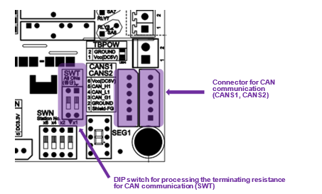
Figure 5.89 Method for the Connection of the Terminating Resistance of the Public 8-Point IO Board (BD587)