5.13.2.1. Digital Input
5.13.2.1. Digital Input
The following figure and table describe the pin configuration of the digital TBI. Each terminal block makes it possible to connect eight different input signals to the same common power.
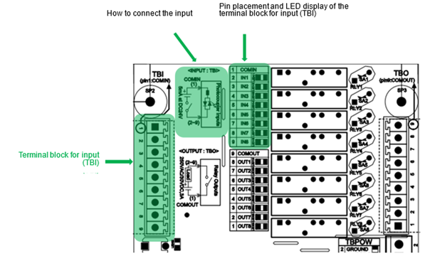
Figure 5.83 Pin Configuration of the Digital Input Terminal Block of the Public 8-Point IO Board (BD587)
Table 5‑44 Pin Configuration of the Digital TBI of the Expansion Public IO Board (BD583)
Pin No. | Signal Name | Signal Description |
1 | COMIN | COMMON power (Ground DC24V or DC24V ) |
2 | DI1 | 1st input of the 1st public input signal port * of the user |
3 | DI2 | 2nd input of the 1st public input signal port * of the user |
4 | DI3 | 3rd input of the 1st public input signal port * of the user |
5 | DI4 | 4th input of the 1st public input signal port * of the user |
6 | DI5 | 5th input of the 1st public input signal port * of the user |
7 | DI6 | 6th input of the 1st public input signal port * of the user |
8 | DI7 | 7th input of the 1st public input signal port * of the user |
9 | DI8 | 8th input of the 1st public input signal port * of the user |
Note *) The 8-point input port of the BD587 board is fixed as the port #1.
The electrical specification of each input signal is as follows.
n Input terminal component: AC input photocoupler
n Rated input signal: DC24V / 5 mA for each point
n Common power: 24VDC or 24VDC Ground / 40 mA
The user is required to connect the input signal according to the method, as shown in the figure below. First, connect the user power +24 V or the ground to the IO board (BD587. Then, connect each signal to the input pin according to the purpose.

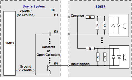
Figure 5.84 Method for the Connection of the Input Signal of the Public 8-Point IO Board (BD587)