3.1.2. Manipulation Buttons
3.1.2. Manipulation Buttons
As the button operating the key function of “HRVision 3D-MultiCam”, each function is as follows.

n Settings
| Menu to set and manage various functions and link H/W. Sets various functions such as camera, exposure, car model, and communication. |

- Camera
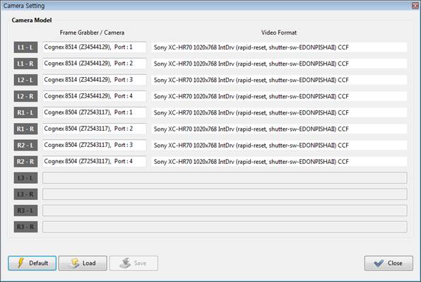
| Sets the camera model and the video format. |

When using a frame grabber and an analog camera, the screen shown below will be displayed.
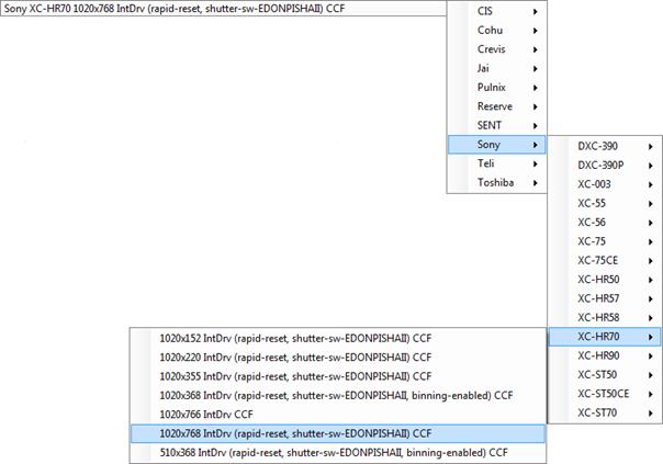
When required to change the camera model and the video format as necessary, it is possible to select the desired items as shown in the screen below.
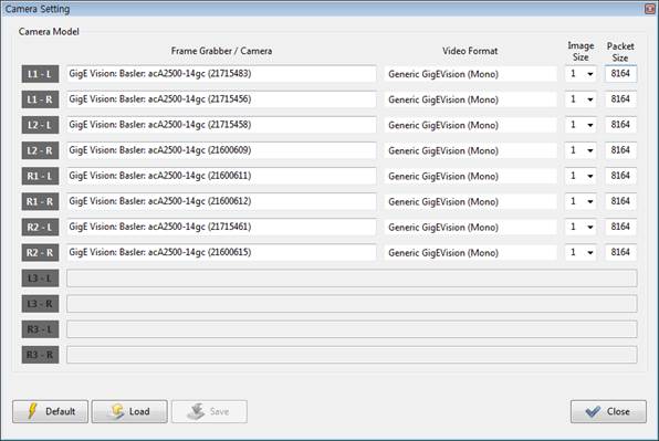
When using a GigE digital camera, the screen shown below will be displayed.
It is possible to change the video format, image size, and packet size.
The image size can be selected between 1 and 1/2. When 1 is selected, the image will be acquired using the resolution of the camera. When 1/2 is selected, the image will be acquired by reducing the camera’s own resolution into half. Even when 1/2 is selected, if the camera does not support this function, the image will be acquired in the camera’s own resolution.
When the packet size is reduced, the speed at which the image data will be transmitted to the PC will be stabilized but will be slowed down. If it is enlarged, the speed will get faster but there is a possibility of instability depending on the network environment. If the nework environment (such as PC specification, switching hubs and Ethernet cards) is not sufficient to transmit the image data of the GigE digital camera, it is required to reduce the packet size.
If 12 cameras will be used, it is possible to select L3-L, L3-R, R3-L, and R3-R cameras.
When required to change the camera model and the video format as necessary, it is possible to select the desired items as shown in the screen below.

- Exposure
| Sets the exposure value of the camera. |

When Registered Exposure is selected as shown in the figure below, the exposure value that was used for pattern registration will be displayed for reading only. When ‘Registered Exposure’ is selected from the Exposure ( ) button on the main screen, this exposure value will be used.

When User Exposure is selected, it will be possible to reset each car model and the camera exposure value. When ‘User Exposure’ is selected from the Exposure ( ) button on the main screen, this exposure value will be used.
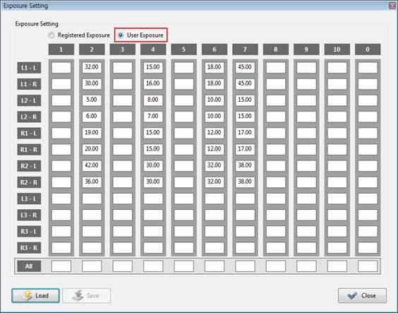
Regardless of the car model, when required to change the current exposure value, change the exposure value of the car model ‘0’. When ‘0’ or none is inputted for the car model on the main screen, this exposure value will be used.
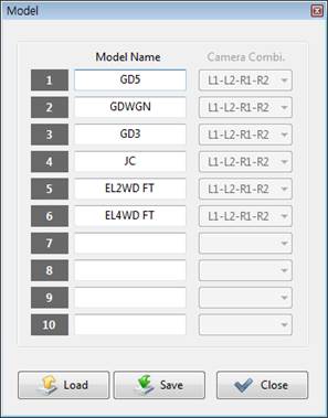
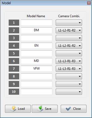
- Model
| Inputs the car model name. |

Inputs the car model name in the space under Model Name
When the measurement points are four, including L1, L2, R1 and R2, Camera Combi. will be disabled, making it unnecessary to select.
When the measurement points are six, including L1, L2, R1, R2, L3 and R3, it is required to select a camera combination for each car model. In Camera Combi., it is possible to select whether to use a combination of L1-L2-R1-R2 or L1-L3-R1-R3.
The figure shown below on the left is a screen to be displayed when the there are four measurement points, while the figure shown below on the right is a screen to be displayed when there are six measurement points.
- Reference Points
| Registers the measured position of the car body as the reference position. |

While a car model that needs to be registered is not inputted, if this is selected, a message window will be displayed as shown below.

In this case, input the car model number in the Model space on the main screen as shown below.

If the measurement to be carried out at six points, including L1, L2, R1, R2, L3, and R3, and the camera combination to be measured is not defined, a message window will be displayed as shown below. Settings – Select the Camera Combi. to be measured in the Model menu.

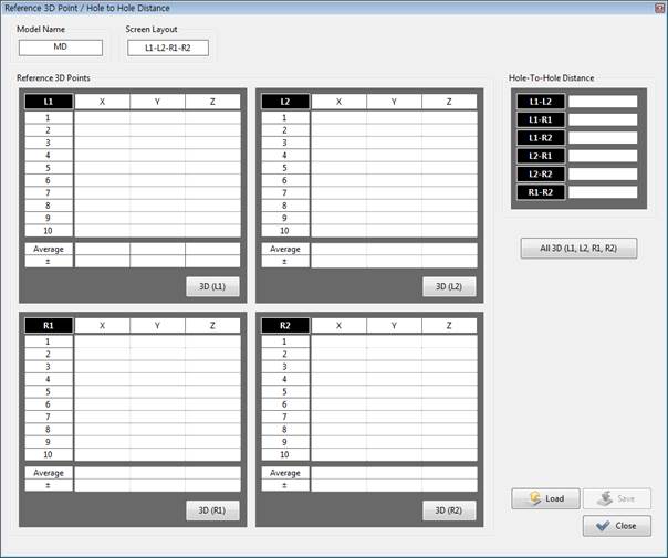
When a screen is displayed as shown below, press the “3D” button relevant to each point. After that, the 3D coordinate relevant to the position will be measured. When the button is pressed continuously, the average value and the repeatability of the measured 3D coordinate will be calculated.
If there is no pattern in a specific camera, a message window similar to the one shown below will be displayed. In this case, it is required to register the camera pattern before carrying out 3D measurement.

When the “All 3D” button is pressed, the 3D coordinate of every point will be measured. If it is pressed continuously, the average value and the repeatability at every point will be calculated automatically.
If the pattern was not recognized properly, a large value of repeatability will be displayed. In this case, register the pattern again.
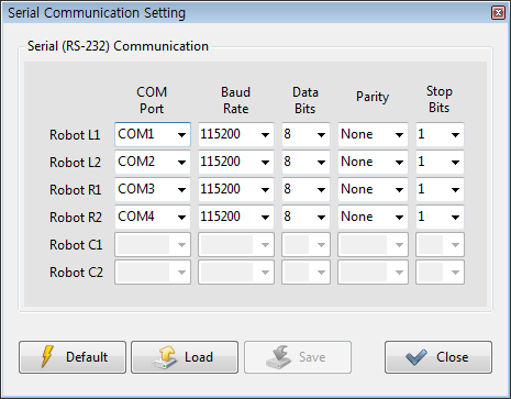
- Communication : Serial (RS-232)
| Use a serial (RS-232) communication for the transmission of data with the robot.. |

In order to transmit data between the PC and the robot through serial (RS-232) communication, set the COM Port, Baud Rate, Data Bits, Parity, and Stop Bits as shown in the figure below.
If the “Save” button is pressed while the serial communication setting is wrong (for example, the same COM port is used for multiple robots), a message window will be displayed as shown in the figure below.

In the same context, if the “Close” button is pressed while the serial communication setting is wrong, a message window will be displayed as shown in the figure below.

In this case, check the setting of the serial communication.
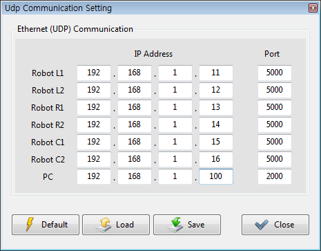
- Communication : Ethernet (UDP)
| Use an Ethernet (UDP) communication for the transmission of data with the robot. |

In order to transmit data between the PC and the robot using an Ethernet (UDP) communication, set the IP and communication port of the robot and the IP and communication of the PC as shown in the figure below. When it comes to the IP address of the robot, input the IP address of the robot controller. When it comes to the IP address of the PC, input the IP address of the PC currently being used. Users can set the ports of the robot and PC arbitrarily.
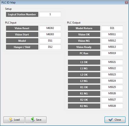
- PLC : Mitsubishi
| Uses a Mitsubishi (MELSEC) PLC. |

In order to use a Mitsubishi (MELSEC) PLC, set the I/O shown below in a way that is proper for PLC.
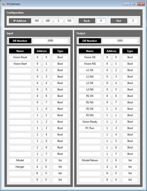
- PLC : Siemens
| Uses a Siemens PLC. |

In order to use a Siemens PLC, set the I/O shown below in a way that is proper for the PLC.
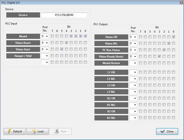
- PLC : Digital I/O
| Uses a PLC by using a digital I/O board. |

In order to use the PLC by using a digital I/O board of Advantech, set the I/O shown below in a way that is proper for the PLC.
- PLC : Non-Use
| Uses no PLC |

- Search Mode : Quick
| Searches a pattern quickly. |

When the “Quick” mode is selected, a basic pattern search method will be used. The speed will get slightly faster than when the “Accurate” mode is selected. Even when the origin of the pattern is set as the center of the circular hole, it is recommended to use the “Accurate” mode for an improved accuracy.
- Search Mode : Accurate
| Searches a pattern accurately. |

When the “Accurate” mode is selected, a basic pattern search will be carried out, and the center of the circular hole will be estimated once more through ellipse fitting Use the “Quick” mode in a case where there is no circular hole in the pattern, the origin of the pattern is not set as the center of the circular hole, or the circular hole is not detected properly because of the surrounding environment.
- Auto 3D Correction : Use
| Calibrates the measured 3D data automatically. |

When “Use” is selected, the measured 3D data will be calibrated and outputtted. Calibrates automatically to minimize the measurement error by calculating the quality of the data measured from individual cameras.
- Auto 3D Correction : Non-Use
| Will not calibrate the measured 3D data. |

When “Non-Use” is selected, the measured 3D data will be outputted without being calibrated. “Use” is recommended.
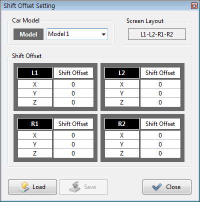
- Shift Offset
| Shifts the value of the measured 3D data. |

When the value of the measured 3D data is lopsided toward the side at a certain amount, the user can do the calibration by shifting it arbitrarily. For example, if the 3D data measured at L1 is lopsided toward the X direction by +10 mm, calibrate as much by inputting -10 mm in the X space of L1.
If a camera is out of the position, causing the value of the 3D data to be lopsided toward a certain position, the Shift Offset function may be used as an emergency measure. However, this function shall be used rarely.
If the value of the 3D data continues to be measured incorrectly, contact the supplier for inquiry.
- Vibration Detection
| Detects the vibration of the car body. |

The vibration of the car body will be detected before the 3D position is measured using cameras. Set the cameras to detect the vibration and the vibration detection variables.
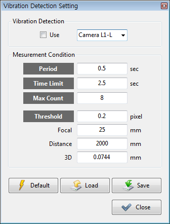
When “Use” is checked, the selected camera will be used to detect the vibration.
“Period”is the measurement cycle. For example, if it is set as 0.5 sec, the measurement will take place every 0.5 sec.
“Time Limit” is the measurement time. For example, if it is set as 2.5 sec, the measurement will take place for 2.5 sec.
“Max Count” is the maximum measurement count. For example, if it is set as 8, the measurement will take place up to 8 times.
If one of the “Time Limit” or “Max Count” condition is met, the measurement will stop.
“Threshold” is used to set the amount of pixels that were vibrating when measuring the same point. 0.2 is the default.
In general, this function is not necessary. However, it is recommended to use this function in an environment where there is a case of severe vibration in a factory.
- Limit
| Sets the error limit of the 3D data. |

In the figure shown below, the “Moving Distance Limit” is the distance limit at which the measured hole may move in space. The “Hole-to-Hole Distance Error” is the error threshold for the hold-to-hole distance.
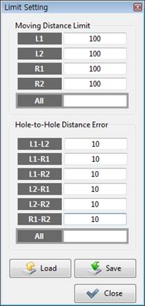
NG will be outputted when the 3D position of the car body moves by more than “Moving Distance Limit” compared with the reference car body.
When the same pattern appears on the car body (for example, only multiple circular holes of same size appear), the cameras could not decide which pattern is the right one. When both L1 and L2 recognize different patterns (holes), there could be a case in which the hole-to-hole distance is the same, while only the hole moving distance is gets larger. If there is a known information that the car body will not change out of a certain range, we may understand that any 3D data exceeding the range (Moving Distance Limit) will be wrong.
While the hole-to-hole distance of the care model A and B is similar, if there is an incorrect command input when looking for a model because of a problem with recognition of car model, it would be impossible to judge whether the car model is wrong only based on the information of “Hole-to-Hole Distance Error.” In this case, when the hole position is different between the car model A and B, and the information of “Moving Distance Limit” is set, it would be possible to know that a wrong car model is inputted.
- Password
| Changes the password. |

First, input the current password. After that, input a new password in the next space and in the lowest space.

If the current password is wrong, a message window will be displayed as shown below.

If the newly inputted passwords are not identical, a message window will be displayed as shown below, and the password will not be changed. recheck whether the new password is correct.

- File Management
| Sets the data storage period and the deletion time. |

Sets the storage period and the deletion time for the OK/NG images and other various data stored while executing the programs.
Considering that deleting data could be a huge burden on the system, it is recommended to set the deletion time during wee hours when the robot is not in operation. Basically, the data, after 30 days, will be deleted at 4 o’clock in the morning.

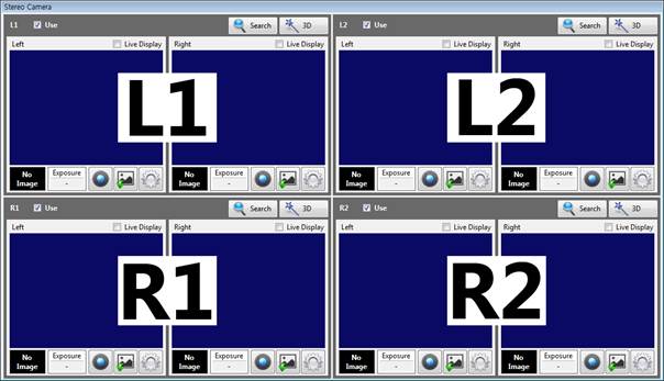
- Screen Layout
| Changes the screen layout. |

The Image Display Window and the Output Window of the HRVision 3D MultiCam program will be differently laid out depending on the layout of the robot and cameras to be used in the process. When there is a total of 4 measurement points, it is possible to choose among the four different screen layouts as shown on the bottom left. When there is a total of 6 measurement points, it is possible to choose among the 8 different screen layouts as shown on the bottom right.


When “L1-L2-R1-R2” is selected, the L1 screen will go on the top left, the L2 on the top right, R1 on the bottom left, and the R2 on the bottom right. The Output Window will be laid out similarly.
n Calibration
| Loads the camera calibration program and calculates the relationship between the robot and the cameras. |

- Camera Calibration
REF _Ref384371457 *r *h * MERGEFORMAT The camera calibration program of 3.2.1 will be loaded, and the camera projection matrix will be calculated.
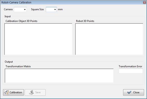
- Robot-Camera Calibration
The relationship between the calibration plate that is used for calibration of cameras and the robot will be calculated.
n Grab
| Acquires individual images shown through the camera whenever clicked one by one. |

n Live
| Displays the images continuously through the installed cameras. |

n Exposure
| Selects among three different exposure modes. |

- Registered Exposure
| Acquires image through the exposure applied when registering a pattern. |

- Auto Exposure
| The nozzle will be changed automatically to ensure that the brightness at the time of registering the patterns is similar to the current image brightness. It is recommended to use the automatic exposure mode. |

- User Exposure
| Acquires images through the exposure set by the user. In case of User Exposure, it is possible to carry out setting in “Settings — Exposure” differently for individual car models and cameras. |

n Search
| Recognizes the pattern after the image is acquired. |

Before calibrating the cameras, use this button to check whether the pattern registration has been carried out properly for all cameras and whether the pattern recognition has been carried out properly.
While the car model is not inputted, if the “Search” button is pressed, a message window will be displayed as shown below.

In this case, input the car model number in the Model space on the main screen.
If there is no pattern registered, an error message will be displayed on the Status window as shown below. In this case, carry out pattern registration first.

If a patter is registered, the result of pattern recognition will be displayed on the screen.
n 3D
| Calculates the 3D position value of the car body. |

Use this button to check whether the 3D position value is correctly calculated at all measurement points.
While the car model is not inputted, if the “3D” button is pressed, a message window will be displayed as shown below.
In this case, input the car model number in the Model space on the main screen.
If a specific camera is not calibrated, a message window similar to the one shown below will be displayed. In this case, calibrate the camera first.

If the relationship between the robot and the cameras is not calibrated, a message window similar to the one shown below will be displayed. In this case, calibrate the relationship between the robot and the camera.

When all the preceding processes are completed, acquiring images, recognizing patterns, and calculating the 3D positions will be carried sequentially, and the 3D measurement results will be outputted.
n Disp. Option
| Decides whether to display the results data, to be acquired after the pattern recognition or the 3D position calculation is completed, on the window for image. |

- Score
| Displays the score of the pattern recognition result. |

- Origin
| Displays the origin of the recognized pattern. |

- Coordinate Axes
| Displays the coordinate axis of the recognized pattern. |

- Pattern Region
| Displays the region of the recognized pattern. |

- Hole
| Displays the detected circular hole when a circular hole is registered. |

- Search Region
| Displays the pattern search area. |

- Origin (Reference)
| Displays the origin of the pattern of the reference car body. |

- Coordinate Axes (Reference)
| Displays the coordinate axis of the reference car body. |

- Pattern Region (Reference)
| Displays the region of the reference car body. |

- Center and Scale Results
| Displays the relative size by comparing the pattern origin and the reference car body. |

- Center Guide Line
| Displays a cross line at the center of the image. |

n Load Pattern
| Loads a registered pattern. |

n Save Image
| Store the current entire screen and images of individual cameras in the “C:*HRVision MultiCam*Image” folder. |

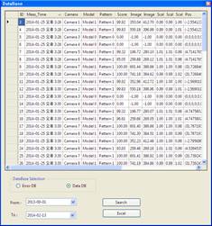
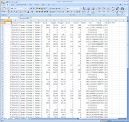
n Database
| Displays a window to search the database of the measured data. |

Displays a window to search the database of the measured data. The searched data can be displayed in link with the “Microsoft Excel” program.
n Manual / Auto
| Changes the Manual/Auto. |

Changes the Manual/Auto. When the mode is changed from Manual to Auto, all the data saved in files will be reloaded. While the data is being loaded, the word “Manual” will change to “Loading,” and after the process is completed, the word will be changed to “Auto.” In “Auto” mode, it is impossible to manipulate all other buttons except for the one used to acquire images. Manipulation will take place only through the communication between PLC and the robot.