3.3. Robot controller’s PROFIBUS master setting
3.3. Robot controller’s PROFIBUS master setting
To set the teaching pendant to use the BD525 PROFIBUS-DP master, the following procedures should be executed:
(1) Select 『[F2]: System』 → 『2: Control parameter』 → 『2: Input/Output signal setting』 → 『15: BD525 fieldbus setting and diagnosis』
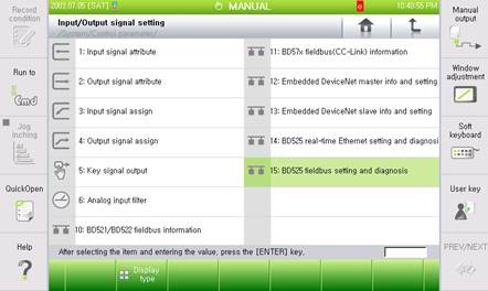
Figure 3.2 BD525 field bus setting and diagnosis menu
(2) Considering that the PROFIBUS-DP master corresponds to the channel 1, use the 『[F3]: Previous』 or 『[F4]: Next』 key to move to the channel 1 and check whether the device type shows “RPOFIBUS-DP master”.
If the device shows “RPOFIBUS-DP master,” it means that the BD525 board is installed normally. If it shows “Not installed,” it means that there is a problem with the installation of BD525. In that case, it is required to check whether the board is installed normally.
In addition, if the function is turned on, the BD525 software version information will be displayed in the bracket of the device type.
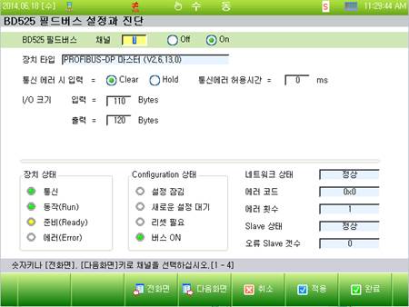
Figure 3.3 PROFIBUS-DP master setting screen
(3) Sets the I/O size.
(4) Sets the input option when there is an error with communication. When the option for processing the input data (FB1.X) is set as clear, all the input data will be cleared to 0 when there is an error with communication. When it is set as hold, the last valid value will be maintained when there is an error with communication
(5) To use the PROFIBUS-DP master function, it is required to shift to the on position before clicking the Apply or Complete button.

l Once the setting is changed, resetting (On è Off è On) or rebooting of the controller should be carried out for the newly set value to be applied.