2.2. PROFIBUS master BD525 setting
2.2. PROFIBUS master BD525 setting
The next is an example of the setting method for using the BD525 PROFIBUS-DP slave for Step 7.
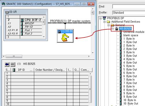
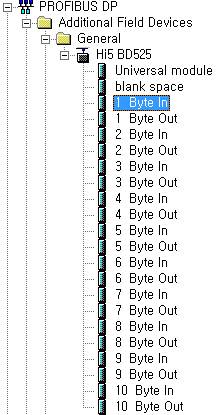
(1) Install the BD525 PROFIBUS-DP slave GSD file (HI5_0A12.GSD). Once installation is completed, Hi5 BD525 will be displayed in the General folder under the Additional Field Devices of the HW Config catalogue window.

(2) Add Hi5 BD525 to the PROFIBUS-DP master device.
(3) The BD525 PROFIBUS-DP slave input and output consist of combination of input or output modules with the size ranging from 1 to 10 byte individually (INPUT=Input data size, OUTPUT=Output data size)
l Input module = 10 byte input module (INPUT/10) unit(s) + (INPUT%10) byte input module 1 unit
l Output module = 10 byte output module (OUTPUT/10) unit(s) + (OUTPUT%10) byte input module 1 unit
Example 1) When the BD525 PROFIBUS-DP slave input and output are 120 byte individually
Þ 10 byte input module 12 units + 10 byte output module 12 units
Example 2) BD525 PROFIBUS-DP slave input and output are 9 byte and 16 byte individually
Þ 9 byte input module 1 unit + 10 byte output module 1 unit + 6 byte output module 1 unit
Example 3) BD525 PROFIBUS-DP slave input and output are 16 byte and 1 byte individually
Þ 10 byte input module 1 unit + 6 byte output module 1 unit + 1 byte output module 1 unit
(4) Set the IO module of BD525. For example, when the input is 32 byte and the output is 64 byte, the module configuration and the slot configuration of HW Config in actual Step 7 will be as shown below.
l Input module configuration (32 byte): 10 byte input module 3 units + 2 byte input module 1
l Output module configuration (64 byte): 10 byte output module 6 units + 4 byte output module 1

l In slot configuration, the input modules must be placed prior to the output modules always.

(5) For more details about other procedures and methods for network configuration, refer to the manual for the master.