3.2. Installing a Welding Gun and Selecting a Tool Frame
3.2. Installing a Welding Gun and Selecting a Tool Frame
Select a library again and call an appropriate welding gun component. Then, mount this gun to the robot.
Tools numbered from 0 to 15 can be assigned as step parameters in the Hi5 controller. As an appropriate tool constant should be applied in the ROBCAD simulation according to the tool number parameter of each step, the connection between devices and tool numbers should be assigned in advance.
Therefore, a frame with an appropriate name in an established form should be attached to the tool end of a device with the tool number used. The form is as shown in [Table 3-1].
Table 3‑1 Type of frame to be attached on tool end
Tool number | Frame name |
T0 | {Robot instance name}_tcpf0 |
T1 | {Robot instance name}_tcpf1 |
… | … |
T15 | {Robot instance name}_tcpf15 |
For example, to process a rectangular jog based on Tool No. 0 or a simulation of work program using Tool No. 0, a frame named hs165_02_tcpf0 should be attached to a corresponding tool end.
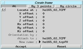
Figure 3.3 Create frame dialog box
When 『Create frame』is selected from the Layout menu, the Create frame dialog box will be displayed. Assign tool end “entity” for the 『Locate at, Attach to』 item, as shown in [Figure 3.3], then assign the name in established form to “New name” and click [Accept]. If the direction of the created frame is incorrect, the direction can be corrected by <Place Editor> in ROBCAD.
In order to teach to the location of frame created when teaching location from the motion dialog box, click the <Settings> tab in the motion dialog box, click the [Tcpf] button as shown in [Figure 3.4], and enter the name of the created frame in the dialog box displayed, as shown in [Figure 3.5].
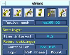
Figure 3.4 Settings tab

Figure 3.5 Assigning Tcpf