6.1. PLC Monitoring
6.1. PLC Monitoring
This is the function to use HRLadder to monitor the current relay value condition of the embedded PLC of the robot controller.
(1) As shown in [Figure6.1], the project file (*.HlPrj) must be opened. Use the 『File – New File』 instruction to create a new project file or use the 『File - Open』 instruction to open an existing project file.

Figure 6.1 Project File Opened Condition
(2) When you press the “Online” button to switch the status to online condition, the saw-toothed wheel icon on the PLC Control Bar will start to move. When this moves, it means that the monitoring operation is working normally. [Table 6-1] describes the meaning of icons of the monitoring operation.
Table 6‑1 Monitoring Image for Operating Status
Icon status | Meaning |
| Communication offline condition |
| Communication online condition. Communication error condition. |
| Communication online condition. Normal communication condition. |
 Separated saw-toothed wheel
 Stopped red saw-toothed wheel
 Rotating saw-toothed wheel
(3) If you want to switch to “Offline” condition, press the “online” button once more time to turn it off.
(4) PLC mode list box located at the right side of the “Online” button displays the current PLC mode and can be used for remote control. In the PLC mode, there are 6 statuses as shown in [Table 6-2].
Table 6‑2 Status of All PLC List Box
PLC Mode | Meaning |
STOP | Ladder operation stopped. Can switch mode only with controller T/P. |
RUN | Ladder operation running. Can switch mode only with controller T/P. |
Remote STOP | Ladder operation stopped. Can switch mode remotely with Remote-RUN from HRLadder |
Remote RUN | Ladder operation running. Can switch mode remotely with Remote –STOP from HRLadder |
PLC OFF | Embedded PLC turned off. (H4a Controller dip s/w #5 OFF or Hi5 Controller application condition PLC OFF) |
NO LAD | No ladder diagram in embedded PLC |
(5) For example, when the embedded PLC is in “remote RUN” or “remote STOP” status, you can remotely switch the mode through the drop down list box as shown in [Figure 6.2].

Figure 6.2 Remote Mode Switch Over with Drop Down List Box
(6) In other cases, it cannot be switched remotely. PLC status list box only shows the current status and does not allow any user operation as shown in [Figure 6.3].

Figure 6.3 Remote Mode Switch Over Disabled Drop Down List Box
(7) Click on the tab located at the bottom of the screen as shown in Figure 6.4 to display the monitoring window. Open the relay type dropdown list box at the top of the monitoring window and select the type to display the relay value.
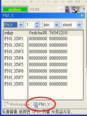
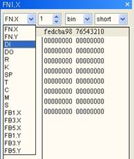
Figure 6.4 Select Relay Type to Monitor
(8) As shown in [Figure6.5], you can open the drop down list box of bit type at the top of the monitoring window to select which type to display the relay value. You can select from bin (Binary), dec (Decimal) and hex (Hexa Decimal) and you can select from 3 types of short, long and float.

Figure 6.5 Select Antilogarithm Expression for Monitoring
(9) When you select FN.X or FN.Y, the control to select the number of FN object is displayed. Type in the number or click on the Spin button (or operate the mouse wheel) to select the FN object.

Figure 6.6 Select FN Object Number
(10) When you want to view several relay types simultaneously, open several windows open. When you select “View (V) –Monitoring” window item from the main menu or click on the tool button  , another monitoring window will appear. Appropriately adjust the location and size and set the relay type dropdown list box.
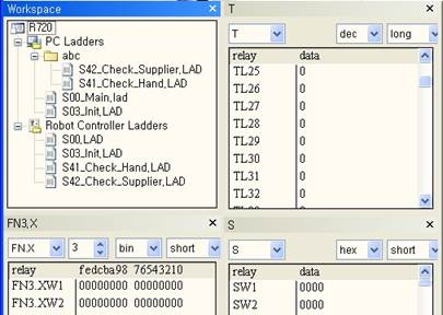
Figure 6.7 Example of Appropriate Arrangement of Opening 4 Monitoring Windows
(11) The relay status is also displayed on the ladder diagram symbol during the monitoring operation. As shown in [Figure6.8], the symbol of “DO18, DO17, DO21” is displayed as short and bold horizontal line, which means that it is activated. Symbol of “DO21” is “XIO (B contact point)”, which means that the “DO21” signal is turned off.
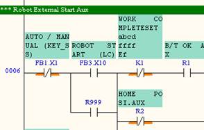
Figure 6.8 Display of Relay Condition of Ladder Diagram Symbol
(12) For the box type instruction, the current relay value is displayed in purple below the operand as shown in [Figure 6.9].

Figure 6.9 Display of Relay Condition of Box Type Instruction
(13) If the embedded PLC is in Stop condition, the monitoring value of operand is not displayed. Also if the ladder diagram is different from the file downloaded from the embedded PLC, the following display of Figure 6.10 appears on the top right corner of the ladder window and the monitoring value of operand is not displayed. That is, only when the ladder is the same as the currently executed ladder, you can analyze the operation of the ladder while viewing the monitoring value of each operand.
(If only the comments are different, it is considered to be the same ladder file.)
The display can disappear as time goes by. If you want to check again, press the F5 key.
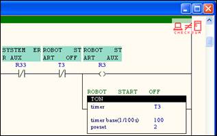
Figure 6.10 When Content of Ladder Window is Different From That of Embedded PLC
(14) If you click on the check sum not equal icon at the top right corner of the ladder window and click on ‘Yes’ for the message box as shown in [Figure 6.11], the monitoring value can be displayed by force.

Figure 6.11 Check Whether to Force to Display Monitoring Value
(15) HRLadder continuously received large amount of monitoring information through the communication cable form the controller. Therefore the refreshing speed of the monitoring information may not feel satisfactory. In order to accelerate the refreshing speed, increase the baudrate in the RS-232C setting. (The setting of the controller must also be adjusted as well.)
Another method is to keep only the relay type that you need to monitor and to disable the monitoring for the other types. When you select 『Tool (T) – Option (O)』 menu, the following dialog box show in [Figure6.12] will be displayed. Only the relay types checked will be monitored. Uncheck any relay types that do not require monitoring. You can gain significant improvements in speed by excluding large scale relay types including “RW” or “KW, TW, CW, DMW, SMW”. For “CW, DMW, SMW”, you can limit the number of data in the edit box on the right side of the check box to improve the communication speed. For the “FB” object, select only the “FB” of the channel in use to improve the communication speed.
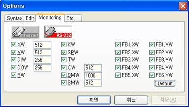
Figure 6.12 Select Relay Range to Monitor