3.2. Connection between the main board and DeviceNet
3.2. Connection between the main board and DeviceNet
The main board CAN port is connected to the small door board through an inner wiring inside the controller via the system board as shown in Figure 3.2.
When the connection to DeviceNet needs to be made through the CAN port of the main board, the DeviceNet communication cable needs to be connected to the user CAN connector of the small door board.
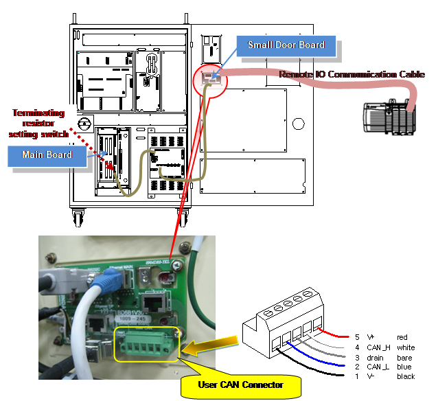
Figure 3.2 Main board CAN port connection with DeviceNet
The user DeviceNet connector of the small door board is an open type 5Pin connector and its pin map is as shown in Figure 3.3.

Female Male
Figure 3.3 Open type connector pin map
If the Hi5 controller is the terminating part, the DIP32 pin of the dip switch of the main board (BD510V10) needs to be set in the On position to turn on the terminating resistor
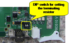
Switch No. | 1 | 2 | |
Setting content | OFF | System CAN terminating resistor off | Embedded DeviceNet terminating resistor off |
ON | System CAN terminating resistor on | Embedded DeviceNet terminating resistor on | |
Switch appearance |
| ||

Figure 3.4 BD510 terminating resistor setting