2.3.2. Setting of BD58AV21 and the connectors
2.3.2. Setting of BD58AV21 and the connectors
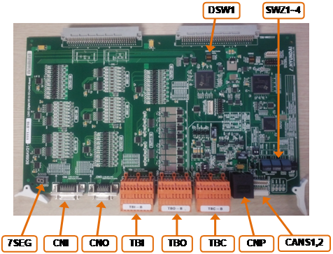
Figure 2.7 LDIO board (BD58A21)
Set by applying the same method that is used for BD570V20.
Table 2‑9 BD58AV21 Setting the station number and the communication speed for BD58AV21
Switch name | Usage | Type | How to set | Setting when shipped |
SW1 | Station number (10 units) |
| Station number set = (SWZ1 setting value x 10) + SWZ2 setting value | “0” |
SW2 | Station number (1 unit) |
| “1” | |
SW3 | Communication speed |
| 0 : 125 kbps 1 : 625 kbps 2 : 2.5 Mbps 3 : 5.0 Mbps 4 : 10 Mbps | “4” |


Table 2‑10 Setting the number of occupied stations of BD58AV2
Switch name | Type | Switch number | How to set the number of occupied stations | Setting when shipped | |||
1 | 2 | 3 | 4 | ||||
SWZ4 |
| 1 (SENYU0) | OFF | ON | OFF | ON | ON |
2 (SENYU1) | OFF | OFF | ON | ON | ON | ||

TBC-A is for the RS232 and RS485 communication, while TBC-B is a terminal block for the CC-Link communication. Connect the CC-Link communication cables as shown in the following table.
Table 2‑11 Terminal configuration of the LD10 board (BD58A) terminal block TBC
Terminal block name | Terminal number | Signal name | Explanation of functions |
TBC - B | 1 | DA | CC-LINK DA line |
2 | DB | CC-LINK DA line | |
3 | DG | CC-LINK ground | |
4 | Shield3 | CC-LINK cable shield | |
5 | FG3 | CC-LINK cable ground | |
6 | DA | CC-LINK DA line | |
7 | DB | CC-LINK DB line | |
8 | DG | CC-LINK Ground | |
9 | Shield3 | CC-LINK cable shield | |
10 | FG3 | CC-LINK cable ground |