2.3.2. Item description
2.3.2. Item description
l Arc sensing: <Disable, Enable>
Set whether to enable or disable arc sensing.
l Left/Right side sensing start cycle: [0~9]
Arc sensing is done in left/right direction and up/down direction based on the weaving surface, and this value sets from which weaving cycle to start the left/right direction sensing. Generally when starting the arc welding, it is recommended to skip 2-3 cycles as the initial welding current is unstable.
l Height sensing start cycle: [4~10]
This sets the up/down direction sensing start cycle, and because the reference value for up/down direction must be set, this must be higher than the left/right sensing value. Generally, if this value is set to about 7 cycle as the current change at the start of the welding is unstable, the up/down sensing is done based on the current value from left/right sensing start cycle to before the up/down sensing start cycle internally.
l Voltage coefficient (mm/dV): [-12.5~12.5]
This value is applied when calculating the calibration distance based on the input value of the welding current, and is calculated based on the equation of 『Calibration distance = Analog input voltage variance (0~12) × Current coefficient』. For current sensing ‘+’ value is entered and for voltage sensing ‘-’ value is entered. This value can differ by the type of current detection device, input range and used current. Therefore, the appropriate value must be calculated based on simple measurement for on-site installation.
Voltage coefficient calculation method
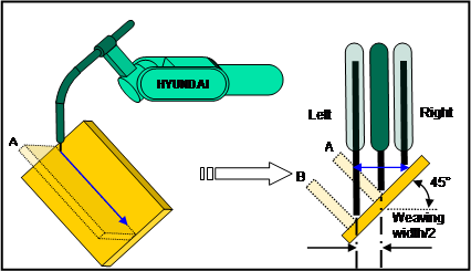
For the following weaving case, the base material is inclined by 45° as shown in the picture. Assuming that A exists, you can calculate the current coefficient by measuring the left/right current value while implementing the actual welding work after teaching the weaving work program that joins the two type of base material. (Refer to data collection function of engineering data). That is, as shown in the above picture, there is no work piece A, and the length of the left wire is longer than that of the right, showing inverted current change. In this case, because the distance for the robot to move due to the current change is the same as when base material existed on location B, the robot must move only by weaving width/2. Therefore you can calculate the 『Current coefficient =(Weaving width/2)/Current value difference』.
Ex) Configure the system to be 500[A] welder, welding current = Within 300[A], side calculation range of arc sensing condition is 0.9, current detection device is CT and ±24V SMPS and resistance of 100[Ω] to collect the data while operating the robot by setting the weaving width of 3X3 [mm].
When the robot actually moves by 3.82 [mm] and the collected value of analog input voltage of left/right direction is 6.046/5.871[V], the voltage difference is 0.175[V] and the『Current coefficient = (Weaving width/2)/Voltage difference =(3.82/2)/0.175 =10.9』.
l Limit tracking distance per sample: [0.00~2.55]mm
Set the maximum value to track in the left/right/up/down direction in the motion sampling cycle for the left/right/up/down calibration calculated based on the current coefficient for each weaving cycle. This value is calculated from the actual weaving width and moving speed as follows.
① Limit tracking distance per sample = (Actual weaving width/2) / (Number of motion sampling per weaving cycle)
For example, actual weaving width = 3.82[mm]
Weaving frequency = 2[Hz]
Welding speed = 60[cm/min],
Number of motion sampling per weaving cycle = 1 / (2[Hz]) /20msec = 25,
Therefore, the calibration distance per sample = 3.82/2/25=0.0764mm.
The above calculated value is a theoretical value and it is not ideal to actually track half of the weaving width in one cycle. Therefore set the actual value lower than the calculated value. The effect of this value is that when it is high, the bead will not be smooth and when low, the tracking angle will be reduced.
If the value calculated based on current coefficient is higher than distance that can be reached in 5 cycles due to the calibration distance limitation per sample, the 『E1194 arc sensing error (Left/Right sensing range exceeded)』 or 『E1195 arc sensing error (Up/Down sensing range exceeded)』.
Reference) For example, if the calibration distance per sample is 0.05[mm],
Weaving frequency = 2[Hz],
Welding speed = 60[cm/min],
② Calibration distance per weaving cycle
= Calibration distance by sample × 1 cycle time / Sampling time
= 0.05[mm] × 1 / (2[Hz]) / 20[msec]
= 0.05[mm] × 500[msec] / 20[msec]
= 1.25[mm],
③ 1 cycle movement
= Welding speed × 1 cycle time
= 60[cm/min] × 1 / (2[Hz])
= 60 × 10[mm] / 60,000[msec] × 500[msec]
= 5[mm],
④ Track angle range
= tan-1 (Calibration distance per weaving cycle / Movement per cycle)
= tan-1(1.25[mm] / 5[mm])
≒ 14[deg]
l Limit tracking distance per cycle: [0.00~2.55]mm
This limits the upper value calculated based on the current coefficient per each weaving cycle. Though the maximum of this value is about half of the actual weaving width, it is recommended to have a slightly lower value than the theoretical value described in the calibration distance per sample.
Reference) For example, calibration distance limit per cycle = 1.2[mm],
Weaving frequency = 2[Hz],
Welding speed = 60[cm/min],
① Movement per cycle
= Welding speed × 1 cycle time
= 60[cm/min] × 1 / (2[Hz])
= 60 × 10[mm] / 60,000[msec] × 500[msec]
= 5[mm],
② Tracking angle range
= tan-1 (Calibration distance per cycle / Movement per cycle)
= tan-1(1.20[mm] / 5[mm])
≒ 13.5[deg] limited to.
l Node calculation point offset: [-9~9]
Arc sensing of Hyundai Heavy Industries sets the interval from the central weaving point to the TOP point and calculate the current value of the TOP point, and this function shifts the point of judgment in left and right direction based on the central weaving point depending on the setting (Negative=Past direction). This is the function to respond to the different response speed of the welding current detector. Generally set this to 0 for use.
l Current abnormality processing method: <Error, End point>
This sets the processing method for abnormal current. If the 『Error』 is set, the 『E1192 arc sensing error (Current range exceeded)』 error occurs when the current input that exceeds the 『Abnormality judgment margin』 exceeds the『Abnormality judgment time』. But when set as the 『End point』, the error does not occur in the above condition and is processed as the end point to stop the movement, and then the next command is executed. Generally the next command is {ARCOF}, and the unit executes crater process from the detected location.
① Abnormality judgment margin: [1.00~1.50]x100%
This sets the margin to judge as abnormal current. Judgment of abnormal current is done based on the past 5 data points.
Upper limit of abnormal judgment = Average of past 5 data points × Abnormal judgment margin,
Lower limit of abnormal judgment = (Average of past 5 data points × 2 )– Upper limit of abnormal judgment
② Abnormality judgment time: [3~200]x10msec
This sets the time to judge as abnormal when the input current exceeds the 『Abnormal judgment margin』. Though this value is an element that decides how fast to judge the recognition of end point, if this is set too low, there is a possibility of judging non-end points as end points. Therefore this must be set accordingly to the environment and generally 10 (0.1 sec) is recommended.
l Sensing trace deviation limit: [0 (disable)~200]mm
This sets the limit value to stop the robot when the welding line tracking by arc sensing exceeds a certain distance. By utilizing this value, you can set the robot not to deviate more than a certain distance from the taught trace from several causes of the welding system.
l Side cal. range / Bead judgment curve: [-1.27~0.00]
This sets the algorithm and value to calculate the side current.
① Arithmetic average algorithm
If this value is set higher than 0, the average value is used for side current calculation, and the value decides how much current to use for the average based on the center of the side weaving interval. That is, if set to 0.9, 45% of the current value of before and after the TOP point is averaged to calculate the side current.
② Curve fitting algorithm
If the above value is set to 0 or a negative number, the curve fitting algorithm is used, and the value decides the sensitivity of the curve. That is, this decides the constant of the 2nd factor. When set to 0, this value means the surface condition without any distinction between the TOP and central point, and when this value is set to negative, this refers to the curve in which the TOP point is sharper than the central points. If you set to -0.02~-0.1 when detecting the bead, you can effectively detect the bead.
Reference) Generally the variance of welding current is high and therefore the use of arithmetic average algorithm is recommended.
l Bead detection: <Disable, Enable>
This function is only valid when using the curve fitting algorithm to calculate the above side current and if the curve form is not satisfied, this sets the operation of the function to judge with bead. If disabled, 『E1192 arc sensing error (Current range exceeded)』 occurs when the number of accumulation exceeds 『Permitted cycle exceeding reference value』 when the TOP current cannot be projected based on the input current. But when this function is enabled, the error is not processed in the above condition. The bead is recognized to stop the movement and then the next command is executed. Generally the next command is {ARCOF}, and the unit executes crater process from the detected location.
l Reference value exceeding permitted cycle : [1~9]
Permitted cycle that exceeds the reference value is used as follows.
① When you cannot calculate the current of the end point when calculating the initial calibration, the calibration cannot be calculated and move onto the next operation repeatedly. When a specific number of times is reached, the 『E1193 arc sensing error (Detected current value too unstable)』.
② When the TOP current of left and right side cannot be calculated, the number of accumulation is limited. The number of accumulation is the running number of errors from the initial error, which increases by one for each occurrence of the error. But if the calculation is normal after that, it decreases by one. That is, when it is continuously normal, it will maintain 0 and the accumulative management starts when the error occurs.
When this reaches the set number of times, the error of 『E1193 arc sensing error (Detected current value is too unstable)』 occurs. You can check the detail error item from the record screen. But, this process judges based on the bead when the bead detection function is enabled and processes as the end point.
③ When the TOP current cannot be calculated as described above, the number of accumulation in the left and right direction is managed separately. When this reaches the set number of times, the error of 『E1193 arc sensing error (Detected current value is too unstable)』 occurs. You can check the information on which side the error is from based on the record screen. This process judges based on the bead when the bead detection function is enabled and processes as the end point.
Caution) If there is tag welding to fixate the base material within the welding interval, you must set the number of times to skip the tag in order to ignore the tag.
l Left-right unbalance sensing ratio : <Disable, Enable>
This is used for tracking the welding line when the welding bead width of left and right sides are different, and set to Enable when you imbalance sensing is required. Left/Right imbalance sensing will proceed based on the degree of initial imbalance.