2.1.5. Setting the Tool InterferenceArea
2.1.5. Setting the Tool InterferenceArea
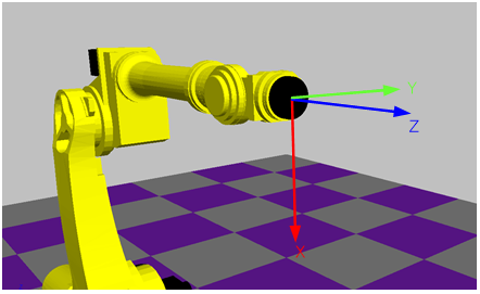
Figure 2.1 Flange Coordinate System
In order to set the tool Interference area for each tool number, use the robot flange coordinate system as the base standard. In the flange coordinate system, when the robot is in the standard position, 'Z' is the outward direction that is vertical to the flange, 'X' is the downward direction, and 'Y' is the left side of the robot.
Each tool number can be set with up to 4 Interference areas. The tool number used in the robot program must be set with the tool Interference area. If this setting is not done, tool interference will not be detected.
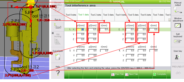
(1) Example of servo gun setting
The tool Interference area can be designated by setting the starting point, ending point, and radius for the coordinate of the tool flange. Each tool number can be set with up to 4 Interference areas.
Refer to this Figure for examples on direction and setting of the flange coordinate system.
(2) Example of hanger setting
l When setting only 1 tool Interference area
When setting only 1 tool Interference area for tools that are not symmetrical based on the flange center, use the method of setting the maximum distance between the tool shape's center and corner as the radius.
In the example below, the robot coordinate system displays the values of X=-175, Y=-485. As for the radius, R1 is the larger between R1 and R2, so set to 1,300, which is slightly higher than 1,250. Setting the radius to 1,300 sets a hemi-sphere in each side of the cylinder, so respectively set P1=(-175,-485,500), P2=(-175,-485,1000) for 'Z' position.
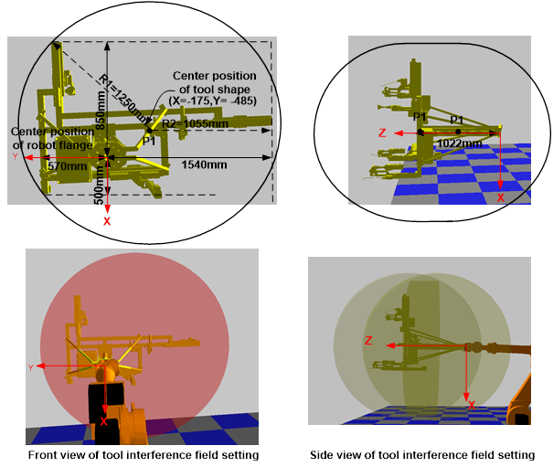
However, it is unavoidable to unnecessarily set a larger value than the tool's actual shape when setting a large radius as above. Thus, several modeling should be conducted when it is necessary to designate detailed tool areas.
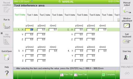
l When setting 4 tool Interference areas
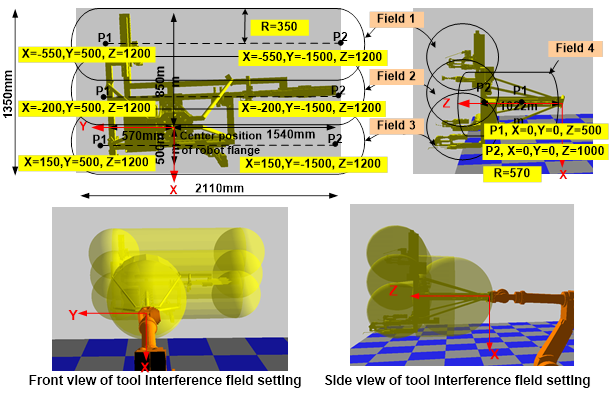
If the tool is large, as with the hanger, setting the fields in partial divisions can help to prevent setting an excessively large tool Interference area. When dealing with a tool of 2,110mm width and 1,350mm length as below, it is possible to divide the vertical fields into three parts and conduct modeling for 3 cylindrical fields (1~3), each with a respective radius of 350mm. Lastly, setting the offset from the flange to the tool as field 4 enables settings as below.