2.1.4. Setting the Arm Interference area
2.1.4. Setting the Arm Interference area
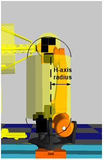
Both sides of the arm Interference area model are comprised of hemi-sphere cylinders. For example, the H-axis can be modeled as shown below by setting the radius from the H-axis joint position to the V-axis joint position.

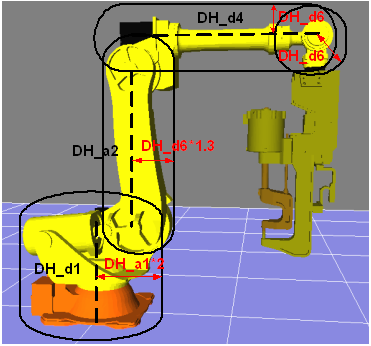
The cylindrical link model for the robot body arm is applicable to S-axis, H-axis, V-axis, and B-axis. The basic radius setting value for each axis has been determined as follows. If additional equipment is mounted on the robot, designate an axis radius higher than the basic value.
l S-axis radius: Set double distance from S-axis rotational center to H-axis joint position
l H-axis radius: Set 1.8 times distance from B-axis rotational center to flange
l V-axis radius: Set distance from B-axis rotational center to flange
Select 『[F2]: System』 → 『4: Application parameter』 → 『7: Interference prevention』→ 『2: Arm interference prevention』 → 『2: Arm interference area』to view the radius currently set as default. To change the default setting, enter the setting value and press “[F7]: Complete”. To return to the default setting, select “[F1]: ALL Initialize”.
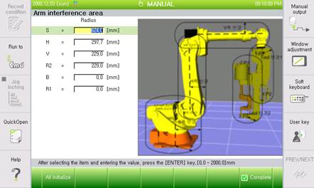
Currently regarding robot arm interference, the setting values for S, H, V-axis can detect all axis.
Take extreme caution when planning to use a value less than the default value.
For example, the H-axis of serial links such as HS165 has an offset to the right of the S-axis center as shown in the Figure above. Since the interference detection field of H-axis is determined based on the segment that connects from the rotational center of S-axis, along the H-axis link and to the rotational center of V-axis as shown above, the radius of H-axis needs to be set to a size that can contain everything from the rotational center of S-axis to the H-axis link.