5.1.2.4. CAN Communications Connector CANS1, CANS2
5.1.2.4. CAN Communications Connector: CANS1, CANS2
For the CAN Communications Connector, there are two identical connectors with the same pin specification, which are installed as shown in Figure 5.7 below. As CAN communication is conducted through cable, with a Daisy Chaining method, it therefore does not matter which side of the connector it is connected to, as it does not affect the operation.
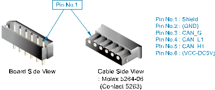
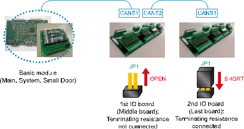
Figure 5.7 Method for the Connection of CAN Connectors of the Public IO Board (BD580)
When connecting several boards, the terminating resistance must be processed precisely. CAN data communication uses the Daisy Chaining method. Therefore, only the board connecting the CAN communication cable at the end must be connected to the terminating resistance; all other boards must not be connected to the terminating resistance. For the connection of terminating resistance, use the JP1 jumper next to the CAN Connectors 1 and 2. When you short-circuit JP1, the terminating resistance is connected, and when opened, the terminating resistance is disconnected.