4.3.7.2. Connector
4.3.7.2. Connector
The following picture shows the layout of the electrical board (BD5C0)’s connectors, and the table shows the uses of each connector and other connection devices.
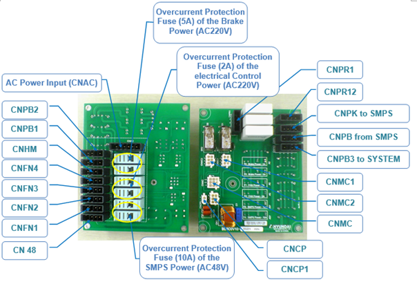
Figure 4.60 Connectors of the Electrical Board (BD5C0)
Table 4‑63 Types and applications of fuses in the electronic control module
Name | Use | External Devices Connection |
CNAC | Various AC power inputs | Transformer |
CN48 | SMPS Power Output (AC48V) | SMPS |
CNFAN1~3 | Power Output (AC220V) for Electrical Drive | FAN Module |
CNHM | Power Output (AC220V) for Hour Meter | Hour Meter (Option) |
CNPR1 | Precharge Resistance Power Input | MC2 Input |
CNPR2 | Precharge Resistance Power Output | MC2 Output |
CNPK | Brake Power Output (AC220V) | Brake Power SMPS Input |
CNPB | Brake Power Input (DC24V) | Brake Power SMPS Output |
CNPB1,2 | Brake Power Output (DC24V) | Servo Amp and Extended Brake Board |
CNPB3 | Brake Power Output (DC24V) | System Board CNPB Input |
CNCP1 | Input of Motor Power Circuit Breaker Monitoring | Motor Power Circuit Breaker |
CNCP | Output of the Monitoring of Circuit Breaker and Fuse | System Board CNCP Input |
CNMC1,2 | The Drive and Monitoring of Magnetic Contactor | Magnetic Contactor MC1, MC2 |
CNMC | Drive Signal and Monitoring Signal for Magnetic Contactor | System Board CNMC |