4.3.7.1. Outline
4.3.7.1. Outline
The electrical module plays a role of opening/closing and distributing various electric powers supplied to the controller. The following picture shows the interior and exterior of the electrical module equipped with various connectors and fuses.
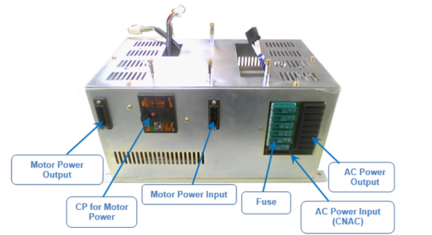
Figure 4.57 Electrical Module


Figure 4.58 The Interior of Electrical Module
The following power flow chart shows the opening/closing of the 3-phase AC power for motor power supply, generation of brake power, AC control power such as fan operation, and the distribution of SMPS power for DC device power supply. Each power supply is equipped with a circuit breaker or fuse to protect components from over current. The electrical board (BD5C0) is used to minimize the use of the cables used for the distribution of power.
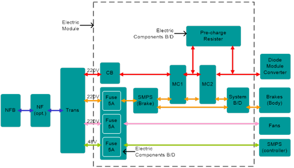
Figure 4.59 Power system of controller Hi5
Table 4‑62 The Sorts and Uses of Fuses in the Electrical Module
Name | Use | Spec. |
F1, F2 | Overcurrent Protection Fuse of the Electrical Control Power(AC220) | AC220V 2A |
F3, F4 | Overcurrent Protection Fuse of the SMPS Power (AC48) | AC220V 10A |
F5, F6 | Overcurrent Protection Fuse of the Brake SMPS Power (AC220) | AC220V 5A |