3.6.3. Example of permitted torque and inertia moment calculation (HS180 Case)
3.6.3. Example of permitted torque and inertia moment calculation (HS180 Case)
(1) Case #1 Simple 2-D model
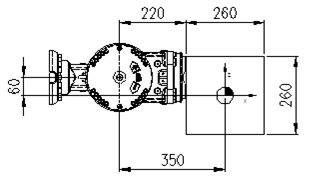
Figure 3.11 2-D load model
M – Load weight
Jxx – Inertia moment in X direction from weight center of load
Jyy – Inertia moment in Y direction from weight center of load
Jzz – Inertia moment in Z direction from weight center of load
Ja4 – Inertia moment from R2 axis rotation center
Ja5 – Inertia moment from B axis rotation center
Ja6 – Inertia moment from R1 axis rotation center
☞ Load condition: Stainless steel with length and width of 260mm and thickness of 260mm (Mass 138.15kg)
① Weight limitation
Load weight : 
② Permitted torque limit
Location of B axis weight center LX = 350mm, LY = 0mm, LZ = -60mm
If you apply the B and R1 axis length limit in the torque map, it is shown as follows
B axis based length 
R1 axis based length 
Load torque of axis B 
Load torque of axis R1 
③ Permitted inertia moment limit
Inertia moment of load from the weight center Jxx= 1.56kgm2, Jyy= 1.56 kgm2, Jzz= 1.56 kgm2
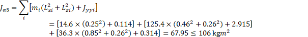
B axis inertia moment (Ja5)

R1 axis inertia moment (Ja6) (Ja6)

④ Conclusion
It is safe because the weight, torque and inertia moment all satisfy the limited condition
(2) Case #2 Complicated 3-D model

Figure 3.12 3-D load model 2-D shape
Combination of block forms of carbon steel (S45C) for the structure of a machinery
(σ=0.0027 g/mm3, : 176.3 kg)
m1 (60×300×300) : 14.6kg
m2 (480×440×220) : 125.4kg
m3 (280×300×160) : 36.3kg
mi - Weight of i block load
LXi - Weight center location in X axis direction of i block
LYi - Weight center location in Y axis direction of i block
LZi - Weight center location in Z axis direction of i block
① Weight limitation
Load weight : 
② Permitted torque limit
You can calculate the weight center location for the total load from the B axis rotation center as follows

 (Symmetric to Y axis)

The weight center location for the total load from the B axis rotation center  = 520.85mm,
  = 0mm,
  = -238.47mm
Distance from the axis B to center of gravity 
Distance from the axis R1 to center of gravity 
Load torque of axis B 
Load torque of axis R1 
x1 y1 z1 – x, y and z direction length of block m1
x2 y2 z2 – x, y and z direction length of block m2
x3 y3 z3 – x, y and z direction length of block m3
LX1, LY1, LZ1 – Weight center location of block m1 from B axis rotation center
LX2, LY2, LZ2 - Weight center location of block m2 from B axis rotation center
LX3, LY3, LZ3 - Weight center location of block m3 from B axis rotation center
Jxx1, Jyy1, Jzz1 – Inertia moment by x, y and z axis from the weight center of block m1
Jxx2, Jyy2, Jzz2 – Inertia moment by x, y and z axis from the weight center of block m2
Jxx3, Jyy3, Jzz3 – Inertia moment by x, y and z axis from the weight center of block m3
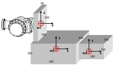
Figure 3.13 3-D load model 3-D shape
③ Permitted inertia moment limit
Table 3‑3 Inertia moment from weight center by block
Block weight [kg] | Weight center (Lx, LY, LZ) [m] | Jxx | Jyy | Jzz |
m1 (14.6) | (0.25, 0, 0) | 0.219 kgm2 | 0.114 kgm2 | 0.114 kgm2 |
m2 (125.4) | (0.48, 0, -0.26) | 2.530 kgm2 | 2.915 kgm2 | 4.433 kgm2 |
m3 (36.3) | (0.89, 0, -0.26) | 0.350 kgm2 | 0.314 kgm2 | 0.509 kgm2 |
B axis inertia moment (Ja5)
R1 axis inertia moment (Ja6)
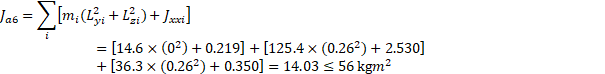
④ Conclusion
It is safe because the weight, torque and inertia moment all satisfy the limited condition