3.6.1. Permitted load torque estimation
3.6.1. Permitted load torque estimation
The load, which will be applied to the mechanical interface of robot's wrist axis, is restricted by
allowable weight, allowable load torque and allowable moment of inertia. The direction of coordinate
system used to calculate the load torque and inertia moment is the same with the direction of robot
base coordinate system. Axis R2 is reviewed in the same manner with the axis B
n Step 1
Calculate the location of the weight center from the B axis rotation center (LX, LY, LZ)
LX: Location of weight center in X axis
LY: Location of weight center in Y axis
LZ: Location of weight center in Z axis
n Step 2
Distance calculation from the axis B and R1 to the center of gravity
 ,
, 
LB : Length from B axis rotation center to weight center
LR1 : Length from R1 axis rotation center to weight center
n Step 3
Calculate the load torque from the calculated distance.


 : Load torque in the rotational center of axis B
 : Load torque in the rotational center of axis R1
 : Mass of load
 : Acceleration of gravity
n Step 4
Check if the load torque calculated in the step 3 is the same with or smaller than the limit value, on the basis of allowed load torque table.
n Note : If the load mass is similar to the mass on the torque curve below, the torque can be
alternatively validated by checking if the distance calculated in the step 2 is distributed in the
torque curve, instead of the step 3 and 4. If it is in the torque curve, the calculated load torque
is smaller than the allowed load torque but if it is out of the torque curve, the calculated load
torque is bigger than the allowed load torque.
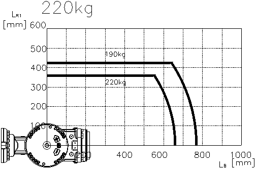
Figure 3.9 Wrist Axis Torque Mapping
 Allowable Load Torque
Table 3‑1 Allowable Load Torque
Maximum Payload | Allowable Load Torque | ||
R2 Axis Rotation | B Axis Rotation | R1 Axis Rotation | |
HS220S | Less than 1,422N·m(145kgf·m) | Less than 770N·m(79 kgf·m) | |