6.4.1. How to Replace Motor
6.4.1. How to Replace Motor
| Attention
Since the robot has a built-in brake inside the motor for keeping the arm posture, the arm will drop when the motor is disconnected. Therefore, in order to prevent the fall, the user must take safety measures such as hanging the arm with a crane, etc. and fix the first and second arms by inserting the fixing bolts. |

(1) Put the controller into TEACH mode and select motors [ON]. When the motors [On] state cannot be obtained, check the respective ARM is firmly fixed while supporting it to prevent dropping. And then begin at step No.4
(2) The axis for which a motor is to be replaced should be put into the basic posture.
(3) Refer to [Figure 6.1 ∼ 6.4] in the case of the main axes (S, H an V).
In the case of the H and V axes, insert a fixing bolt to prevent the arm from dropping.
In the case of the wrist axes (R2, B and R1), set the origin by using the scale of each axis.
(4) Turn the main power [OFF] with the controller power [OFF]
(5) Disconnect the connector from the motor
(6) Remove attachment bolts of motor and pull the motor out of robot. When removing motors of axis H or V, be sure not to damage the lip of oil seal due to the gear attached to the axis of motor
(7) Detach the gear from the motor shaft. Not give excessive impact to the motor shaft
(8) Assemble the gear after lightly applying grease to the shaft
The bolt used to attach the gear to the shaft should be cleaned and removed of grease before using. Apply Loctite 243 to the screw part of the bolt, and then tighten it using a torque wrench in a regular torque. Besides, slowly tighten the bolt in a symmetrical order
(9) Assemble the motor on the robot after applying a small amount of grease to the lip of oil seal and applying a moderate amount of grease to the teeth of gear. When assembly the main axis motor, be sure not to damage the lip of oil seal
(10) Connect the connector to the motor
(11) When replacing the axis H or V, replenish the grease as the amount as it lost
(12) Reset the encoder of the axis whose motor is replaced
 Warning
Before encoder correction, check motor connections, with motors [ON], while pressing the Enable switch for 2~3 seconds.
(1) Perform the encoder calibration about the axis whose motor is replaced. Refer to the chapter [Encoder Calibration] in the controller operating manual.
(2) Remove M20 bolt, a supporting bolt for preventing possible dropping of axis H, V.
(3) Confirm that there is no error in robot's motion.

Figure 6.1 1 Arm (H axis) fixing bolt insertion position
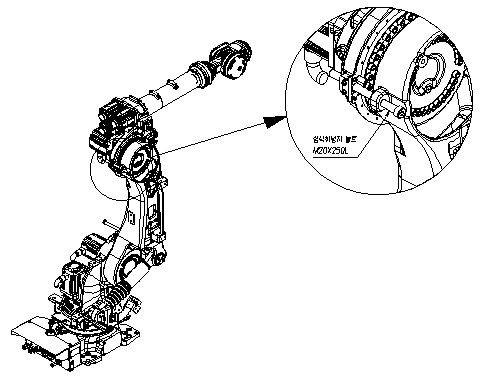
Figure 6.2 2 Arm (V axis) fixing bolt insertion position

Figure 6.3 Motor assemblies of the H and V axes
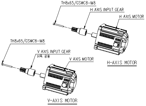
Figure6.4 Motor assemblies of the H and V axes
| Caution
If the entire upper arm is not completely attached to the mechanical stopper in a gravitational direction when replacing the motor of the V-axis, the upper arm may rotate when the motor is being dismantled. |

Figure6.5 Motor assemblies of the wrist axes