3.6.3. Example of permitted torque and inertia moment calculation
3.6.3. Example of permitted torque and inertia moment calculation
(1) Case #1 Simple 2-D model

Figure 3.9 2-D load model
M – Load weight
Jxx–Inertia moment in X direction from weight center of load
Jyy–Inertia moment in Y direction from weight center of load
Jzz–Inertia moment in Z direction from weight center of load
Ja4- Inertia moment from R2 axis rotation center
Ja5- Inertia moment from B axis rotation center
Ja6- Inertia moment from R1 axis rotation center
☞ Load condition: Stainless steel with width, depth, and thickness of 292 mm each (Mass 141.3kg) (Mass 141.3kg)
① Weight limit
Load weight: 
② Limit of the allowable torque
Position of the center of gravity based on the B axis: LX = 366 mm, LY = 0 mm and LZ = -76 mm
The distance from the B and R1 axes to the center of gravity is calculated as follows.
Distance based on the B axis: 
Distance based on the R1 axis: 
Load torque of the B axis: 
Load torque of the R1 axis: 
③ Limit of the allowable moment of inertia
Moment of inertia of the load at the center of gravity
Jxx= 2.83 kgm2, Jyy= 2.83 kgm2, Jzz= 2.83 kgm2
Moment of inertia of the B axis (Ja5)

Moment of inertia of the R1 axis

④ Conclusion
It is safe because the weight, torque and inertia moment all satisfy the limited condition.
(2) Case #2 Complicated 3-D model

Figure 3.10HS165 3-D load model 2-D shape (HS210E)
Aluminum block shape combination
(σ=0.00287 g/mm3, : 201.3 kg)
m1 (60×300×300) 15.5kg
m2 (520×440×220) 144.5kg
m3 (300×300×160) 41.3kg
mi - i Weight of i block load
LXi - i Weight center location in X axis direction of I block
LYi - i Weight center location in Y axis direction of I block
LZi - i Weight center location in Z axis direction of I block
⑤ Weight limit
Load weight : 
⑥ Permitted torque limit
You can calculate the weight center location for the total load from the B axis rotation center as follows

 (Symmetric to Y axis)

The weight center location for the total load from the B axis rotation center Lx = 546.4mm, Ly = 0mm, LZ = -240.0mm
Distance from B axis to center of gravity 
Distance from R1 axis to center of gravity 
B axis load torque 
R1 axis load torque 
x1 y1 z1 – x, y and z direction length of block m1
x2 y2 z2 – x, y and z direction length of block m2
x3 y3 z3 – x, y and z direction length of block m3
LX1, LY1, LZ1 –Weight center location of block m1 from B axis rotation center
LX2, LY2, LZ2 - Weight center location of block m2 from B axis rotation center
LX3, LY3, LZ3 - Weight center location of block m3 from B axis rotation center
Jxx1, Jyy1, Jzz1 –Inertia moment by x, y and z axis from the weight center of block m1
Jxx2, Jyy2, Jzz2 –Inertia moment by x, y and z axis from the weight center of block m2
Jxx3, Jyy3, Jzz3 –Inertia moment by x, y and z axis from the weight center of block m3
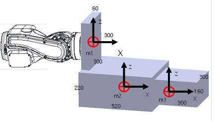
Figure 3.11 3-D load model 3-D shape
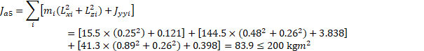
⑦ Permitted inertia moment limit
Table 3‑3 Inertia moment from weight center by block
Block weight (kg) | Weight center(LX, LY, LZ) | Jxx | Jyy | Jzz |
m1 (15.5) | (0.25, 0, 0) | 0.232 kgm2 | 0.121 kgm2 | 0.121 kgm2 |
m2 (144.5) | (0.48, 0, -0.26) | 2.913 kgm2 | 3.838 kgm2 | 5.586 kgm2 |
m3 (41.3) | (0.89, 0, -0.26) | 0.398 kgm2 | 0.398 kgm2 | 0.620 kgm2 |
B axis inertia moment (Ja5)
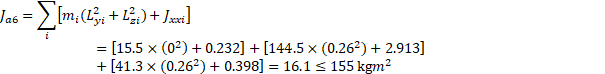
R1 axis inertia moment (Ja6)
⑧ Conclusion
It is safe because the weight, torque and inertia moment all satisfy the limited condition.