3.6.3. Example of permitted torque and inertia moment calculation
3.6.3. Example of permitted torque and inertia moment calculation
(1) Case #1 Simple 2-D model
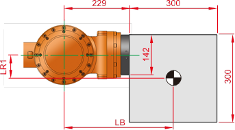
Figure 3.11 HS165 2-D load model
M – Load weight
Jxx – Inertia moment in X direction from weight center of load
Jyy – Inertia moment in Y direction from weight center of load
Jzz – Inertia moment in Z direction from weight center of load
Ja4- Inertia moment from R2 axis rotation center
Ja5- Inertia moment from B axis rotation center
Ja6- Inertia moment from R1 axis rotation center
☞ Load condition: Stainless steel with length and width of 300mm and thickness of 200mm (Mass 141.3kg)
① Permitted torque limit
Location of B axis weight center LX = 379mm, LY = 0mm, LZ = -79mm
If you apply the B and R1 axis length limit in the torque map, it is shown as follows.
B axis based length 
R1 axis based length 
② Permitted inertia moment limit
Inertia moment of load from the weight center Jxx= 1.53kgm2, Jyy= 2.12 kgm2, Jzz= 1.53 kgm2
B axis inertia moment (Ja5)

R1 axis inertia moment (Ja6)

③ Conclusion
It is safe because the weight, torque and inertia moment all satisfy the limited condition.
(2) Case #2 Complicated 3-D model
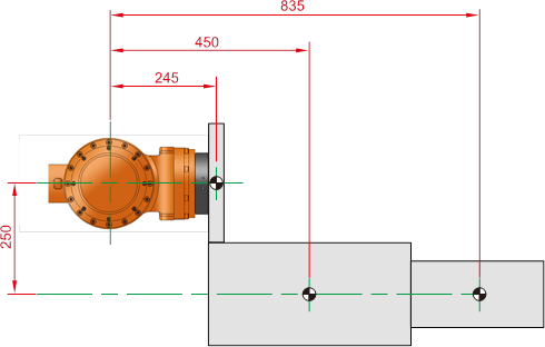
Figure 3.12 HS165 3-D load model 2-D shape
Aluminum block shape combination
(σ=0.00287 g/mm3, : 164.7 kg)
m1 (60×300×300) : 15.5kg
m2 (470×400×200) : 107.9kg
m3 (300×300×160) : 41.3kg
mi – Weight of i block load
LXi – Weight center location in X axis direction of I block
LYi - Weight center location in Y axis direction of I block
LZi - Weight center location in Z axis direction of I block
① Permitted torque limit
You can calculate the weight center location for the total load from the B axis rotation center as follows.

 (Symmetric to Y axis)

The weight center location for the total load from the B axis rotation center Lx = 527.3mm, LY = 0mm, LZ = -226.5mm
If you apply the B and R1 axis length limit in the torque map, it is shown as follows.
B axis based length  → torque value 945.4Nm
R1 axis based length  → torque value 37.2Nm
x1 y1 z1 – x, y and z direction length of block m1
x2 y2 z2 – x, y and z direction length of block m2
x3 y3 z3 – x, y and z direction length of block m3
LX1, LY1, LZ1 – Weight center location of block m1 from B axis rotation center
LX2, LY2, LZ2 - Weight center location of block m2 from B axis rotation center
LX3, LY3, LZ3 - Weight center location of block m3 from B axis rotation center
Jxx1, Jyy1, Jzz1 – Inertia moment by x, y and z axis from the weight center of block m1
Jxx2, Jyy2, Jzz2 – Inertia moment by x, y and z axis from the weight center of block m2
Jxx3, Jyy3, Jzz3 – Inertia moment by x, y and z axis from the weight center of block m3
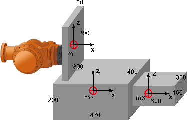
Figure 3.13 HS165 3-D load model 3-D shape
② Permitted inertia moment limit
Table 3‑3 Inertia moment from weight center by block
Block weight (kg) | Weight center (Lx, LY, LZ) | Jxx | Jyy | Jzz |
m1 (15.5) | (0.245, 0, 0) | 0.232 kgm2 | 0.121 kgm2 | 0.121 kgm2 |
m2 (107.9) | (0.45, 0, -0.25) | 1.799 kgm2 | 2.346 kgm2 | 3.425 kgm2 |
m3 (41.3) | (0.835, 0, -0.25) | 0.398 kgm2 | 0.398 kgm2 | 0.620 kgm2 |
Ex) Calculating the inertia moment by axis from the weight center of block m1


B axis inertia moment (Ja5)

R1 axis inertia moment (Ja6)
