3.6.1. Permitted load torque estimation
3.6.1. Permitted load torque estimation
The load, which will be applied to the mechanical interface of robot's wrist axis, is restricted by allowable weight, allowable load torque and allowable moment of inertia.
n Step 1
Calculate the location of the weight center from the B axis rotation center (LX, LY, LZ)
LX: Location of weight center in X axis
LY: Location of weight center in Y axis
LZ: Location of weight center in Z axis
n Step 2
Check the location from the center of B and R1 axis to the weight center based on the torque map.
 ,
, 
Length in B axis (LB) ≤ 0.606 m
Length in R1 axis (LR1) ≤ 0.303 m
LX: Location of the weight center in X axis direction from the B axis rotation center
LY: Location of the weight center in Y axis direction from the B axis rotation center
LZ: Location of the weight center in Z axis direction from the B axis rotation center
LB : Length from B axis rotation center to weight center
LR1 : Length from R1 axis rotation center to weight center
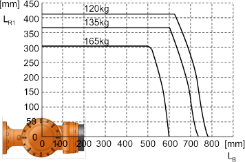
Figure 3.7 Wrist Axis Torque Mapping:[HS165]
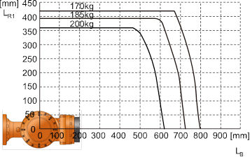

Figure 3.8 Wrist Axis Torque Mapping:[HS200]
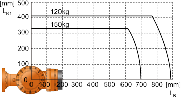
Figure 3.9 Wrist Axis Torque Mapping:[HS150L]
 Allowable Load Torque
Table 3‑1 Allowable Load Torque
Robot Model | Allowable Load Torque | ||
R2 Axis Rotation | B Axis Rotation | R1 Axis Rotation | |
HS165/HS150L | Less than 1,030N·m(105kgf·m) | Less than 490 N·m(50 kgf·m) | |
HS200 | Less than 1,333N·m(136kgf·m) | Less than 706 N·m(72 kgf·m) | |