3.5.2. Example of permitted torque and inertia moment calculation (HA006B Case)
3.5.2. Example of permitted torque and inertia moment calculation (HA006B Case)
[Figure 3.7, 3.8] shows the possible range of where the material point can be located when it is considered that the load to be attached is in the material point. However, since the actual load (End Effector) does not almost always exist at the material point, evaluate the moment of inertia of each axis. For example, when considering the load to be attached as the material point,
(Example) The robot type is [HA006B] and the load weight is 5.74kg

Figure 3.8 2-D load model
M - Load weight
Jxx - Inertia moment in X direction from weight center of load
Jyy - Inertia moment in Y direction from weight center of load
Jzz - Inertia moment in Z direction from weight center of load
Ja4 - Inertia moment from R2 axis rotation center
Ja5 - Inertia moment from B axis rotation center
Ja6 - Inertia moment from R1 axis rotation center
☞ Load condition: Aluminum block (Mass 5.74kg) with a width of 100mm, a length of 100mm and a thickness of 200mm
① Permitted torque limit
B-axis center of gravity position LX = 155mm, LY = 0mm, LZ = -25.5mm
Apply the B and R1 axis distance limits in the torque map as shown below.
Based on B axis 
Based on R1 axis 
② Permitted inertia moment limit
Inertia moment of load from the weight JXX=0.024kgm2, JYY=0.01kgm2, JZZ=0.024kgm2
B axis inertia moment (Ja5)

R1 axis inertia moment (Ja6)

③ Conclusion : It is safe because the weight, torque and inertia moment all satisfy the limited condition.
n Permissible center position from the center of R1 axis
① Permissible center position when viewed from the permissible torque
LR1 ≤ (Allowable torque) / (Load weight)
LR1 = 5.9 N·m / (5.74Kg×9.8 m/s2) = 0.104 m
② Permissible center position when viewed from the permissible moment of inertia
LR1 ≤ (Permitted inertia moment / Load weight)1/2
= (0.06 kg·m2 / 5.74kg)1/2 = 0.102 m
These results is restricted by the distance allowed torque in the shaft center in R1 it is within the 0.102 m.
n Permissible center position at the center of B axis
(This robot is located on the same axis as the B axis, and the permissible load torque and allowable moment of inertia are the same for the B axis and R2 axis. Therefore, when the allowable condition of the B axis is satisfied, the allowable condition of the R2 axis is also satisfied..)
① Permissible center position when viewed from permissible torque
LB ≤ (Allowable torque) / (Load weight)
LB = 9.8 N·m / (5.74Kg×9.8 m/s2) = 0.174 m
② Permissible center position when viewed from the permissible moment of inertia
LB ≤ (Permissible moment of inertia / Load weight)1/2
= (0.27 kg·m2 / 5.74kg)1/2 = 0.217 m
These results are regulated by the distance allowed torque on the B axis in, it will be within 0.174m.
n Torque Map
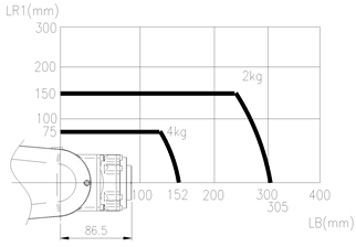
Figure 3.9 Wrist axis Torque lead : [HH4L]
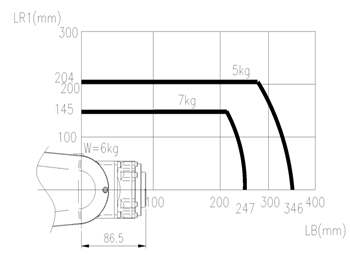
Figure 3.10Wrist axis Torque lead : [HH7]

Figure 3.11Wrist axis Torque lead : [HH7E]
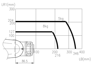
Figure 3.12Wrist axis Torque lead : [HH8]