2.2. External Fixed Vision
2.2. External Fixed Vision
The instructions given in this section apply only to V2.3.0 or higher. | ||
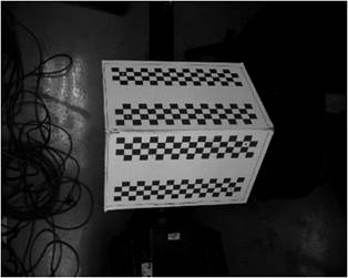
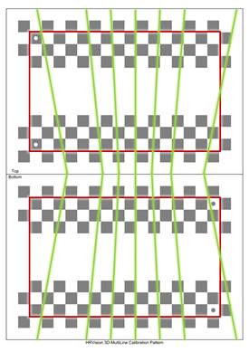
[Step 1] (1) Attach the correction plate properly to the correct robot’s axis. (The correction plate shall be attached to the R1 axis of the robot. Do not attach it to another axis.) (2) The correction plate should not move on the robot’s axis until the calibration is complete. (The relationship [position and orientation] between the correction plate and the robot tool shall be fixed at all times.) | ||
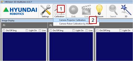
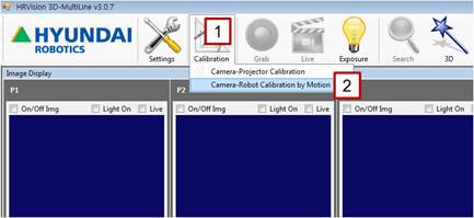
[Step 2] (1) In the main menu, click the [Calibration] button. (2) Select the [Camera-Projector Calibration] menu. | ||
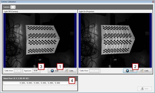
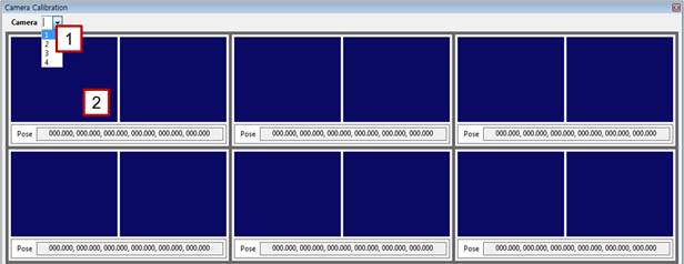
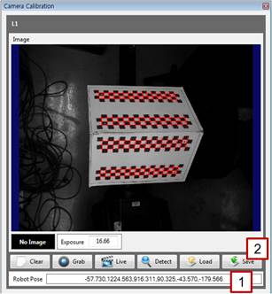
[Step 3] (1) Select the number of the camera to be calibrated. | ||
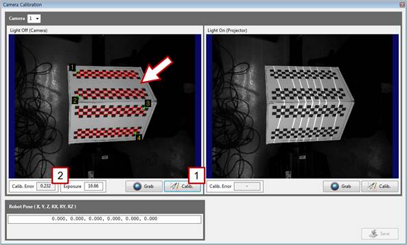
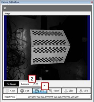
[Step 4] (1) Turn off the pattern light of the projector, click the left [Grab] button, and check the focus and brightness of the image. (2) Turn on the pattern light of the projector, click the right [Grab] button, and check the focus and brightness of the image. (3) As needed, enter a camera exposure value in the [Exposure] column to adjust the exposure to an adequate brightness. (4) Do not enter any values in [Robot Pose] if the camera is fixed on the outside. | ||
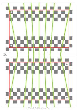
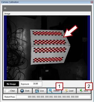
[Step 5] (1) Check whether the seven lines drawn by the projector are in the effective area (between the red rectangles) of the correction plate. (2) If any line is out of the effective area, adjust the correction plate to an adequate position and orientation, and repeat the procedure starting from [Step 4].
| ||
[Step 6] (1) Click the left [Calib.] button, and check whether the corners of the correction plate are properly detected on the left window. (They are indicated by red cross marks.) (2) Typically, the value of [Calib. Error] does not exceed 1.0. When the value exceeds 1.0, the detection accuracy of the correction plate may be low because the focus and brightness of the are not adequate or because the position and orientation of the correction plate are not adequate.
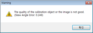
(3) When the warning shown above appears, the mechanical fabrication of the correction plate or the attachment of the correction plate paper is wrong. Therefore, the correction plate should be prepared again before conducting the calibration.
| ||
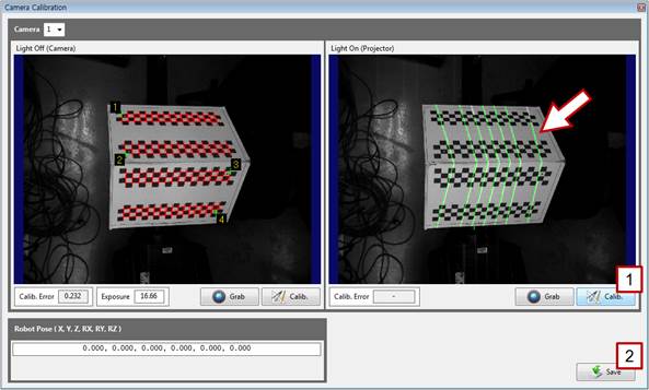
[Step 7] (1) Click the right [Calib.] button. (2) On the right window, check whether the pattern light is properly detected. If it is properly detected, click the [Save] button, and close the window. If not, repeat the procedure starting from [Step 4]. | ||
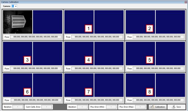
[Step 8] (1) In the main menu, click the [Calibration] button. (2) Select the [Camera-Robot Calibration by Motion] menu. | ||
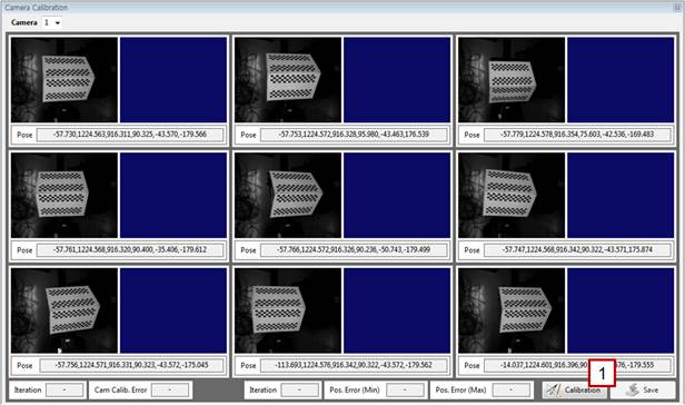
[Step 9] (1) Select the number of the camera to be calibrated. (2) Click the left image on the first window to open a new window. The position of the robot and the correction plate for the first image shall be the same as those used in [Steps 2–7]. In other words, the robot or the correction plate should not be moved to another position or orientation. | ||
[Step 10] (1) Click the [Live] button, and check the focus and brightness of the image. (2) As needed, enter a camera exposure value in the [Exposure] column to adjust the exposure to an adequate brightness. | ||
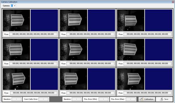
[Step 11] (1) Click the [Detect] button, and check whether the correction plate is properly detected on the screen. (2) If it is properly detected, click the [Save] button, and close the window. If not, repeat the procedure starting from [Step 10]. (3) Record the current position of the robot with the teach pendant. | ||
[Step 12] (1) Perform the procedures in [Steps 10–11] for the other eight points by moving the robot to change the position and orientation of the correction plate. The correction plate for the different poses (position and orientation) should be detected at no less than three points. The calibration will not run if only the position of the correction plate is changed without any changes in its orientation. It is recommended to detect the correction plate at no less than seven points by changing its orientation using the RX-, RX+, RY-, RY+, RZ-, and RZ+ buttons on the teach pendant. | ||
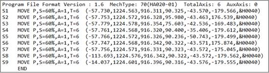
[Step 13] (1) When the images of the correction plate have been acquired, store the robot’s job file corresponding to the images of the correction plate in the PC using a USB flash drive or an application such as HRView. (2) If the coordinate system of the recorded points is set at axial angle or encoder, convert it to another adequate coordinate system. | ||
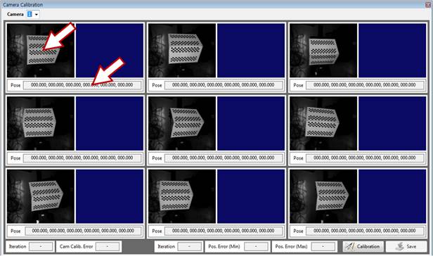
[Step 14] (1) Click the window where the correction plate is detected or the [Pose] section.
| ||
[Step 15] (1) Enter the robot’s pose corresponding to the image of the correction plate in the [Robot Pose] section. In the case of a robot with seven or more axes, enter only up to six axes (X, Y, Z, RX, RY, and RZ). (2) Click the [Save] button, and close the window. | ||
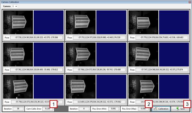
[Step 16] (1) For the remaining images of the correction plate, repeat [Steps 14–15], and click the [Calibration] button. | ||
[Step 17] (1) The arithmetic operation may take some time. Wait until the “Wait for a while.” message window disappears and the “Calibration finished.” window appears. | ||
[Step 18] (1) Typically, the value of [Cam Calib. Error] will be no larger than 0.5. (2) The error between a pose calculated by the camera and that recorded in the robot will not typically exceed 1 mm. Check the [Pos. Error (Max)] value. A high pose error may occur if the robot manipulator is not properly calibrated, if the robot is of a large size, if the distance between the camera and the correction plate is large, or if the angle of the correction plate is highly slanted. (3) Click the [Save] button to store the calibration result. (4) Return to [Step 9], and repeat the same procedure for the remaining cameras. | ||
|