2.1. Wrist-Held Vision
2.1. Wrist-Held Vision
The instructions given in this section apply only to V2.0.12 or lower. | ||
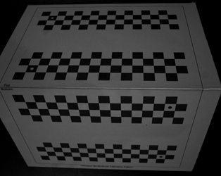
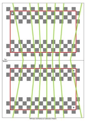
[Step 1] (1) Securely position the correction plate on the outside. (2) The correction plate should not move until the calibration is complete. (The relationship [position and orientation] between the correction plate and the robot base shall be fixed at all times.) | ||
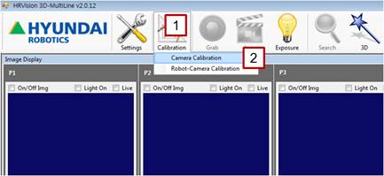
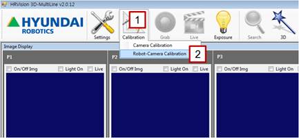
[Step 2] (1) In the main menu, click the [Calibration] button. (2) Select the [Camera Calibration] menu. | ||
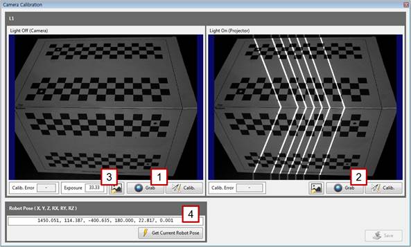
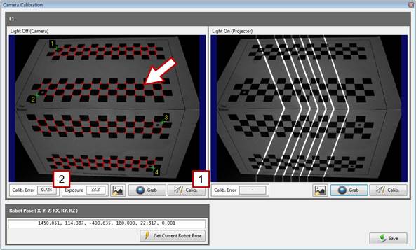
[Step 3] (1) Turn off the pattern light of the projector, click the left [Grab] button, and check the focus and brightness of the image. (2) Turn on the pattern light of the projector, click the right [Grab] button, and check the focus and brightness of the image. (3) As needed, enter a camera exposure value in the [Exposure] column to adjust the exposure to an adequate brightness. (4) Enter the current pose of the robot in the [Robot Pose] column. If only one robot is used, enter the robot’s pose recorded in the base coordinate system. If multiple robots share a coordinate system, enter the robot’s pose recorded in the user coordinate system. | ||
[Step 4] (1) Check whether the seven lines shown by the projector are in the effective area (between the red rectangles) of the correction plate. (2) If any line is out of the effective area, adjust the correction plate to an adequate position and orientation, and repeat the procedure starting from [Step 3].
| ||
[Step 5] (1) Click the left [Calib.] button, and check whether the corners of the correction plate are properly detected on the left window. (They are indicated by red cross marks.) (2) Typically, the value of [Calib. Error] will not exceed 1.0. When the value exceeds 1.0, the detection accuracy of the correction plate may be low because the focus and brightness of the camera are not adequate or because the position and orientation of the correction plate are not adequate.
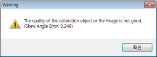
(3) When the warning shown above appears, the mechanical fabrication of the correction plate or the attachment of the correction plate paper is incorrect. Therefore, the correction plate should be prepared again before conducting the calibration.
| ||
| ||
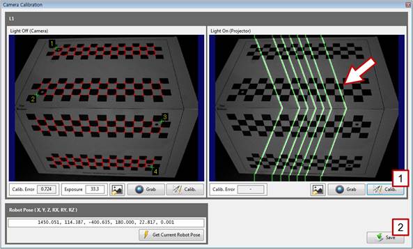
[Step 6] (1) Click the right [Calib.] button. (2) On the right window, check whether the pattern light is properly detected. If it is properly detected, click the [Save] button, and close the window. If not, repeat the procedure starting from [Step 3]. | ||
[Step 7] (1) In the main menu, click the [Calibration] button. (2) Select the [Robot-Camera Calibration] menu. | ||
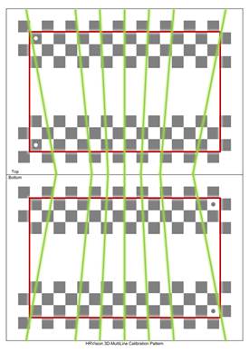
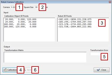
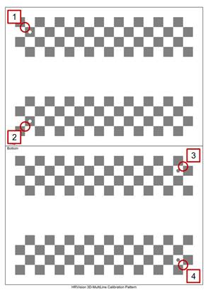
[Step 8] (1) Select a camera number. If only one camera is used, select [1 (L1)]. (2) Select the square size of the correction plate. Typically, [10 mm] is selected. If the user has fabricated a different-sized correction plate, select a matching square size. (3) Teach the four points of the correction plate; extract only the values of X, Y, and Z; and enter them in the [Robot 3D Points] column. For the positions and sequence of teaching, refer to the following figure.
(4) Select the [Calibration] button. (5) Typically, the [Transformation Error] will not exceed 1 mm. When the value is larger, the correction plate may be incorrectly printed (the size of the checkered rectangle of the correction plate does not conform to the specified value), the teaching may be incorrectly executed, or the robot may be incorrectly calibrated. As such, recheck these points. (6) If all the settings are correct, save the setting by clicking the [Save] button, and close the window. | ||
|