4.2. Uniaxial load cell (from Burster) and serial communication module (from Beckhoff)
4.2. Uniaxial load cell (from Burster) and serial communication module (from Beckhoff)
This section describes the serial communication module (RS232) from Beckhoff and uniaxial load cell from Burster. Refer to it with the function manual.
① Components: Uniaxial load cell (amp connected), serial communication module (RS232), and serial cable (RS232)
② Measuring ranges of sensors: The model and measuring range of the amp-connected models are shown in Table 1. Set Fd within the range by referring to this table.
Table 4‑2 Measuring range of load cell
Sensor | Measurement range |
8532-5500 | 0 ~ 500 N |
8532-6001 | 0 ~ 1 KN |
8532-6002 | 0 ~ 2 KN |
8532-6005 | 0 ~ 5 KN |
8532-6010 | 0 ~ 10 KN |
8532-6020 | 0 ~ 20 KN |
③ Attachment of sensor: To use the uniaxial load cell, install it in a manner that the +Z direction of the tool coordinate system and that of the uniaxial load cell in Fig. 1 match.
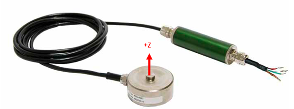
Figure 4.5 Coordinate system of sensor
④ Connection of serial communication module: The serial communication module consists of RS232 coupler (BK8100), bus terminal (KL3100), and bus end terminal (KL9010). Assemble them in the order of RS232 coupler, bus terminal, and bus end terminal. Then, set the address setting terminals on the communication module (X1 to 1 and X10 to 0).
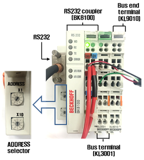
Figure 4.6 Serial communication module
⑤ Connection of load cell line: Connect the signal and power lines of the load cell to the communication module by referring to Fig. 2 and Table 2.
Table4‑3 Wiring between the load cell and communication module
| Load cell | Serial communication module |
Signal line (+) | White line | But terminal 1 |
Signal line (-) | Green line | But terminal 2 |
Power (+) | Red line | 24 V terminal of RS232 coupler |
Power (-) | Black line | 0 V terminal of RS232 coupler |
⑥ Power connection: Connect the power of the serial communication module to the power of the robot controller in order to supply power to the serial communication module and the load cell. As the load cell and serial communication module require 24 V, connect the 24 V and 0 V terminals of the serial communication module to which the load cell is connected to those of the controller, respectively,
⑦ Connection of serial cable: Connect the serial port of the serial communication module and serial port #2 of the robot controller using the serial cable. Use a cross cable with a length of under 15 m as the serial cable.
⑧ Checking of indicators: With the signal, power, and serial cables connected, supply power to the robot controller to check if the green LED of serial communication module would be turned on, as shown in Fig. 2. If the red LED is turned on with the force control, check the connection and communication settings of modules.
⑨ Communication setting: Set the communication setting of serial port #2 by referring to section 2.2.B of the function manual and Table 3.
Table 4‑4 Serial communication setting
Baudrate | 38400 |
Number of characters | 8 |
Stop bit | 1 |
Parity bit | Even |
Echo | Disabled |
Use of port | Sensor |
Communication type | RS232 |
⑩ Command setting: The uniaxial load cell only measures the force (to press the sensor) in the -Z direction of tool coordinate system, so set the force control commands based on the Z direction of the tool coordinate system. By referring to the section 2.5 of function manual and Table 4, set suitable parameters for each command.
Table 4‑5 Command parameter
ForceCtrl | CRD | Reference coordinate system | § Not applicable | |
T | Force control tool number | § Not applicable | ||
BC | Bias Clear | § Set BC to 1 if the tool does not come in contact with any external object. | ||
FCset | Fd | § Set the +Z-directional pressurization. | ||
Dmp | Dt | Set the Z-directional value. | ||
Dr | Not applicable | |||
LIMIT | POS | § Setting of robot operation area under force control, based on the starting position of force control [mm] § Reference coordinate system: Robot coordinate system | ||
VEL | § Setting of max. robot operation speed under force control [mm/s] § Reference coordinate system: Tool coordinate system | |||