4.1. 6-axis force/torque sensor (from ATI)
4.1. 6-axis force/torque sensor (from ATI)
This is about the Ethernet-based 6-axis force/torque sensor manufactured by ATI. Refer to it using the function manual.
① Components: 6-axis force/torque sensor, net box, sensor cable, power supply, and LAN cable
② Measuring ranges of sensors
Table 4‑1 Measuring range of 6-axis force/torque sensor
Sensor | Delta | Theta | Omega |
Axes | SI660-60 | SI2500-400 | SI7200-1400 |
Fx, Fy(±N) | 660 | 2500 | 7200 |
Fz(±N) | 1980 | 6250 | 18000 |
Tx, Ty(±Nm) | 60 | 400 | 1400 |
Tz(±Nm) | 60 | 400 | 1400 |
③ Attachment of sensor: Attach the sensor in a manner that the coordinate system of the sensor, as shown in Fig. 1, matches the one (Xs, Ys, Zs) marked at the end of the robot as shown in Fig. 2.
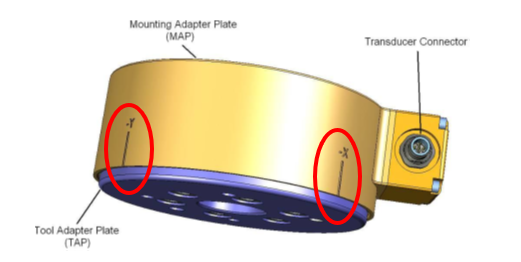
Figure 4.1 Coordinate system of sensor

Figure 4.2 Coordinate systems of sensor (Xs, Ys, Zs) and robot (Xr, Yr, Zr)
④ Cable connection: Connect the force sensor with the net box, and the net box with the robot controller using the sensor and LAN cables, respectively.
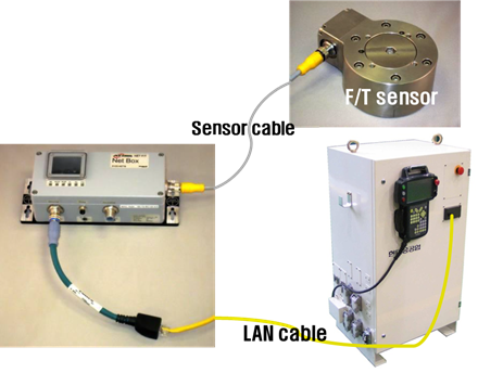
Figure 4.3 Sensor-net box-robot controller cable connection
⑤ Power connection: Connect the power cable to the net box to supply the power (24 V). Check the indicators of the net box. If the cables and power were correctly connected, the indicator would be as shown in Fig. 4. If not, check the cable and power connections again.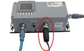

Figure 4.4 Checking of power connection to net box and indicators