2.3. Air purging process
2.3. Air purging process
1) If you turn on the main power of the Hyundai Robot Controller, the air-purging process will be actuated, and high-pressure air will flow into the robot’s body through the purging valve for 3 min to prevent pressure explosion. At this time, inspect whether the controller stops booting until the air-purging operation is completed. Furthermore, check whether an error would occur in the sensor that detects the air-pressure condition while the controller is on standby for purging completion. Figure 2.4 shows the flowchart of the air-purging sequence.
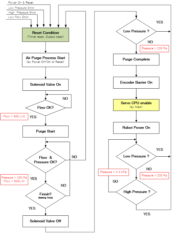
Figure 2.4 Air Purge Sequence Flow Chart
2) Figure 2.5 shows the timings at which the explosion-prevention sensors are actuated and the error conditions that occur during the air-purging process.
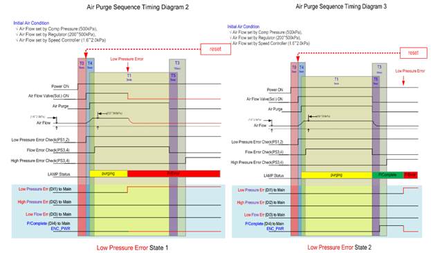
Figure 2.5 Air purging process and detailed timing diagram
3) During air purging, no manipulation should be made. “Air purging in progress” will be displayed at the lower right part of the teach pendant window at this time.
4) When air purging is completed, the controller will start booting and enter the self-diagnosis mode to enable inspection and operation of the system.
5) If air pressure error occurs during air purging, “Purging Error!!!” will be displayed at the lower right part of the teach pendant window even though the controller will start booting and enter the operating state. You will not be able to apply motor driving power to the robot before the error is corrected.
6) After the error is corrected, click [RESET] on the teach pendant window without turning off and on the controller power. This will simultaneously start the air purging process and reboot the controller.
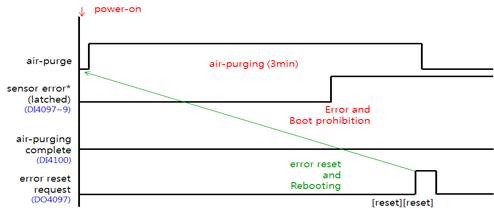
Figure 2.6 Reboot process in case of an error while booting
§ The sensor error will be activated if either the “air pressure low,” “air pressure high,” or “flow rate abnormal” error is input to Ports 1–3 (DI4097–DI4099) of the BD530 TBI0 connector.
§ After air purging is completed, the “air purging complete” signal will be input in Port 4 (DI4100) of the BD530 TBI0 connector, and the signal will be activated under normal condition.
§ The errors and input signals of the “purging complete” sensor can be checked if you click “[F1]: Service” → “1: Monitoring” → “2: I/O Signal” → “1: Dedicated Input Signal” in the conditions of the painting application. Then, the monitoring window will open, allowing you to view the input state of “Pressure Sensor (low)” or “Pressure Sensor (high)” at the lower part of the window.
§ After an air purging error has occurred, click [RESET][RESET] to reset the error. Then, the signal will be output to Port 1 (D04097) of the BD530 TBI0 connector, and the air purging controller will also be reset.
§ The reset signal can be checked if you click “[F1]: Service” → “1: Monitoring” → “2: I/O Signal” → “1: Dedicated Input Signal” in the conditions of the painting application. Then, the monitoring window will open, allowing you to view the “Purge Reboot” output state at the lower part of the window.