2.2. Purging system
2.2. Purging system
1) The purging system of the painting robot controller is as shown in Figure 2.1. The modules include a purging condition display part, a purging control unit, a pneumatic unit, air hoses, and a pressure sensor.
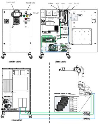
Figure2.1 Air purging system of the painting robot controller
2) The setup of the pressure gauge for air purging, the operating condition lamp, and the pneumatic device is shown in Figure 2.2


Figure 2.2 Setup and operating condition display of the air-purging pneumatic devices
3) Table 2-1 describes the pressure criteria, display, and operating condition lamps needed for air purging.
Table2‑1 Pressure setting and operating condition display for air purging
PRESSURE GAUGE & Regulator | This indicates the pneumatic pressure input to the purging control pneumatic circuit. The input pressure should be set at 0.2–0.3 Mpa with the regulator on the pneumatic device as shown in Figure 2.2. |
PURGE COMPLETE LAMP | This is switched on after air purging. |
PURGING LAMP | This is switched on during air purging. |
PURGE ERROR LAMP | This is switched on in case of errors during air purging. |
4) Figure 2.3 shows the BD5D0 board used for air purging control. It carries out air purging for a given time after the main power is switched on. The air purging time setting is fixed when the controller is delivered. If you need to change the setting, refer to the maintenance manual of the controller.
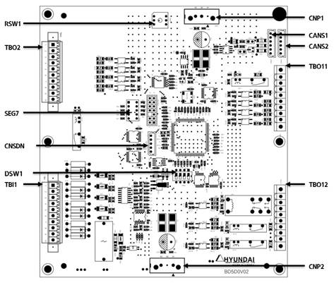
Figure 2.3 Air purging control board (BD5D0)
Table2‑2 BD5D0 connector type and purpose
Name | Use | Spec |
CNP1 | Power supply for control | 5V |
CNP2 | 24V I/O power supply | 24V/5A SMPS |
TBI1 | Pressure switch connection | 24V IO Power |
TBO11 | Connecting the status indication lamp | 24V IO Power |
TBO12 | Signal control for the air-purging valve | 24V IO Power |
TBO2 | Signal of the purging status | BD530 TBIO |
For the connection of each signal, you may refer to the Purging Control Connection (R63-012227-0.0) drawing among the electrical drawings.
Monitor the pressure switch to check the pressure condition inside the robot’s body. The operating condition of the switch can be visually checked with the LED placed next to the TBI1 connector.
Table2‑3 Description of the pressure sensor (TBI1) connector
Terminal No. | Signal name (TBI 1) | setting pressure | Signal Description |
1, 2 | PS1+, PS1- | 180Pa | Low Pressure Sensor 1 |
3, 4 | PS2+, PS2- | 200Pa | Low Pressure Sensor 2 |
5, 6 | PS3+, PS3- | 5.2kPa | High Pressure & Flow Sensor 1 |
7, 8 | PS4+, PS4- | 4.4kPa | High Pressure & Flow Sensor 2 |
9, 10 | - | - | Not Used |
The purging sequence can be checked by the controller front door lamp.
Table2‑4 Description of the lamp output (TBO11) connector signals
Terminal No. | Signal name | Signal Description |
TBO11, 3 | P/Error | Red: Error during the purging operation |
TBO11, 5 | Purging | Yellow: Purging operation in progress |
TBO11, 6 | P/Complete | Green: Purging operation completed normally |
It controls the pneumatic output through the solenoid valve according to the purging sequence and electrically connects the encoder and the servo board by actuating the encoder relay board when the purging is completed normally.
Table2‑5 Description of the signals of the valve and relay control (TBO12) connector
Terminal No. | Signal name | Signal Description |
TBO12, 3 | EVP1- | Solenoid Valve On/Off |
TBO12, 5 | EnRLY_PWR | Encoder Barrier Relay On/Off |
It transmits the current status to BD530 through the I/O.
Table2‑6 Description of the status output (TBO2) connector signals
Terminal No. | Signal name (TBO2) | Signal name (TBIO) | Signal Description |
TBO2, 6 | M_DI 1 | DI 1 | Low Pressure Error |
TBO2, 7 | M_DI 2 | DI 2 | High Pressure Error |
TBO2, 8 | M_DI 3 | DI 3 | Low Flow Error |
TBO2, 9 | M_DI 4 | DI 4 | Purge Complete |
TBO2, 2 | M_DO 1 | DO 1 | Board reset |

§ The air purging function will work normally if the application of the robot controller is set at “Painting.” See the method for application setting described in Section 3.1 Basic (application) setting.
§ For the details of errors and how to troubleshoot the errors that may occur during the air purging, see Section 5.1 Error messages.
§ Ensure that the air pressure needed for the air purging will be maintained within the specified range.