2.2. Operation of signal keys
2.2. Operation of signal keys
Press [SHIFT]+[Manual Output] to show the configured signal keys at the bottom.
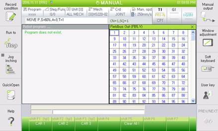
Figure 2.4 Key signal output setting screen
Press [SHIFT]+[F1]–[F7] to operate the signal keys (or tap the signal buttons on the screen with the [SHIFT] key pressed).
The [tgl] on top of the button indicates that it is a toggle button, whereas the rest are push buttons.
As shown in Figure 2.3, yellow lighting indicates that it is ON. The forward signal works with the signal key turned ON. The positive signal is turned OFF, and the negative signal works with the signal key turned OFF.


Figure 2.5 Key signal ON and OFF states

Figure 2.6 Keys prohibited in the auto mode
Signal keys with the "Allow for Auto Mode" option deselected will be marked with gray labels in the auto mode. While in this state, pressing any key would not trigger any operation.
Signal keys with the "OFF When Switching to the Auto Mode" option selected will automatically be turned OFF when switching from the manual to the auto mode.
ø The signal keys momentarily control the output signals when it is turned ON and OFF. The ON/OFF state of the signal keys are not monitored to maintain the output values. For example, if the output signal is turned ON because the signal key is turned ON, it can be turned OFF by the robot language, embedded PLC, or manual output. That is, the output signal may be turned OFF even if the signal key is ON.
ø Positive and negative signals can be used together to facilitate setting of the controls of a double-action solenoid.
ø It can be output as a negative logic or pulse by interlocking with output signal attributes, whereas more complicated controls can be controlled with the signal keys by interlocking it with an embedded PLC.
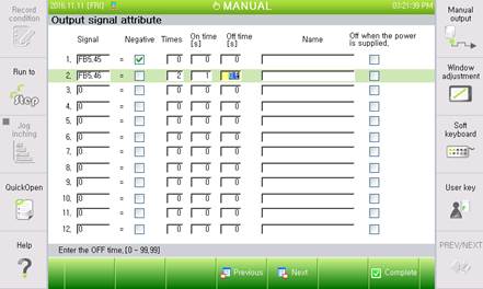
Figure 2.7 [F2: System] – 2: Control parameter – 2: Input/output signal setting – 2: Output signal attibute