2.1. Setting
2.1. Setting
[F2: System] – 2: Control parameter – 2: Input/output signal settings – 5: Select the key signal output menu.
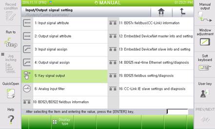
Figure 2.1 Key signal output setting menu
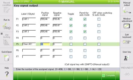
Figure 2.2 Key signal output setting screen
As shown in Figure 2.2, you can set for seven keys ([F1]–[F7]). The setting items are shown in Table 2-1.
Table 2-1 Setting items of key signal output items
Item | Description | Remarks |
Label | Character string to display on the buttons | Within 12 bytes (12 alphanumeric, 6 Korean characters) |
Positive signal | Output signal with the button ON (yellow ON) | Hardwired, field bus (FB), and embedded field bus (FN) can be used. |
Negative signal | Output signal with the button OFF (yellow OFF) | |
Toggle | Toggle button type, with it selected | Toggling between ON and OFF |
Push button type, with it deselected | Pushing for ON and releasing for OFF | |
Permit for auto mode | If the button operations are allowed even in the auto mode |
|
OFF when switching to auto mode | Buttons are automatically turned OFF when switching from the manual to the auto mode, with it selected. |
|
After finishing setting, press [F7: Finish] to save it.
ø Table 2-2 shows the examples of entering positive and negative signals.
Table 2-2 Examples of entering positive and negative signals
Type | Example | Input Result |
Hardwired | 61 | DO61 |
Field bus (FB) | 5.27 | FB5.DO27 |
Embedded field bus (FN) | 2.15 | FN2.15 |
ø The assigned output signal is not controlled by the key signal output, and cannot be set as the positive and negative signal. However, the key signals are not handled as assigned signals.

Figure 2.3 Message to indicate an assigned signal