1.2. Exterior of the BD525 Board
1.2. Exterior of the BD525 Board
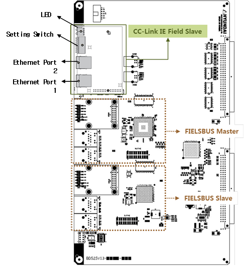
Figure 1.1CC-Link IE Field Communication Board
The BD525 multi-protocol communication board can support up to three industrial communication channels simultaneously, including CC-Link IE Field slaves, fieldbus or real-time Ethernet masters and slaves. For other fieldbus or real-time Ethernet than CC-Link IE, refer to the relevant protocol functional manual.
The CC-Link IE Field Slave communication board is piggybacked on the BD525 board and has a setting switch, four LEDs, and two Ethernet ports.
※ Reference) CC-Link IE Field slave is supported in a BD525 board of hardware version V1.3 or later.
(1) Setting Switch
You can select the node number and LED indication items by using the setting switch. If the pins #1 ~ #7 of the switch are all on (setting value = 127), the node number value set in the main board will be used as the node number and can be changed by using the teach pendant. (Please refer to 3.1 CC-Link IE Slave Setting)
If the setting value of the pins #1 ~ #7 of the switch is within the range of 1 ~ 120, the node number value set by using the switch will be used as the node number and cannot be changed by using the teach pendant.
When the pin #8 of the switch is on, LED3 and LED4 will respectively indicate the link status of the Ethernet port.
If pin 8 of the switch is off, LED3 and LED4 will respectively indicate data transmission / reception status.
Table 1‑1 Setting Switch
| Description | Remarks | ||
Pin number | Usage | Value | ||
1~7 | Node number | 0 | Error (Error LED on) | The change will be reflected after the power is reset. |
1~120 | Node number | |||
121~126 | Error (Error LED on) | |||
127 | Node number setting by TP (Default) | |||
8 | LED indication | 1(On) | LED3: Link1, LED4: Link2 | The change will be reflected immediately. |
0(Off) | LED3: RD. LED4: SD (Default) | |||

(2) LED
Table 1‑2 LED Status
| Description | ||
Number | Indication | Status | |
1 | Run | Off | - No power supplied - No network detected - Network timed out |
Green | - Normal operation | ||
| Error | Off | - Normal operation - No power supplied |
Red | - Station in abnormal operation - Node number duplicated - Master parameter error - Abnormal station address during initialization | ||
Red blinking | - Link error | ||
3 | RD LED (Setting switch pin 8 = Off) | Off | - No data received - No power supplied |
Green | - Data received | ||
Link 2 (Setting switch pin = On) | Off | - No data linked - No power supplied | |
Green | - Ethernet link connected | ||
4 | SD LED (Setting switch pin = Off) | Off | - No data transmitted - No power supplied |
Green | - Data transmitted | ||
Link 1 (Setting switch pin = On) | Off | - No data linked - No power supplied | |
Green | - Ethernet link connected | ||
