4.3. Ethernet/IP scanner setting
4.3. Ethernet/IP scanner setting
The following procedure should be observed to set the teach pendant to use the Ethernet/IP scanner.
(1) Select 『[F2]: System』 → 『2: Control parameter』 → 『2: Input/Output signal setting』 → 『14: Real time Ethernet setting and diagnosis』.
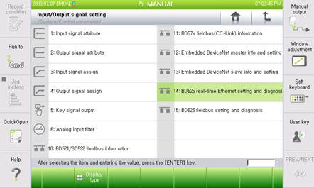
Figure 4.2 Real time Ethernet setting and diagnosis menus
(2) As the Ethernet/IP scanner corresponds to the channel 1, use the 『[F3]: Previous』 or 『[F4]: Next』 key to shift to the channel 1, and then check whether Device Type shows “Ethernet/IP Scanner”.
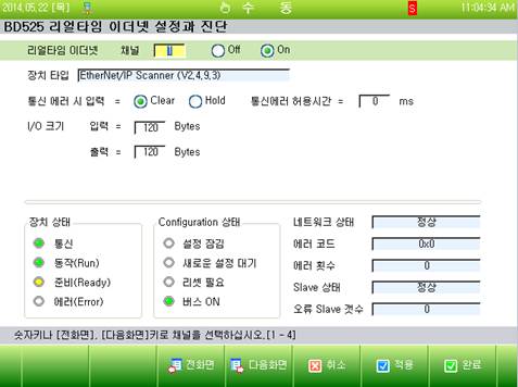
Figure 4.3 Ethernet/IP scanner setting screen
(3) Can select an option regarding how to handle the input when a communication error occurs. When the option is set as “Clear”, the input data (FB1.X) will be cleared to be “0. On the contrary, if it is set as “Hold”, the last valid value that is to be generated when the error occurs will be maintained.
(4) In order to use the Ethernet/IP scanner, shift it to the “On” position and then click the “Apply” or “Complete” button.