3.1. Ethernet/IP adapter setting
3.1. Ethernet/IP adapter setting
It is required to set an IP address and the size of input and output data to use an Ethernet/IP adapter as shown in the following procedure.
(1) Select 『[F2]: System』 → 『2: Control parameter』 → 『2: Input/Output signal setting』 → 『14: Real-time Ethernet setting and diagnosis』.
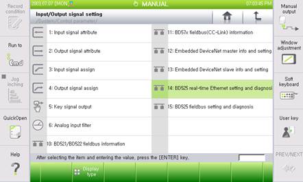
Figure 3.1 Real time Ethernet setting and diagnosis menus
(2) As the Ethernet/IP adapter corresponds to Channel 3, Use the 『[F3]: Previous』 or 『[F4]: Next』key to shift to Channel 3 and then check whether the Device Type shows “Ethernet/IP Adapter”. In the bracket after the device type, the BD525 board firmware version will be displayed.
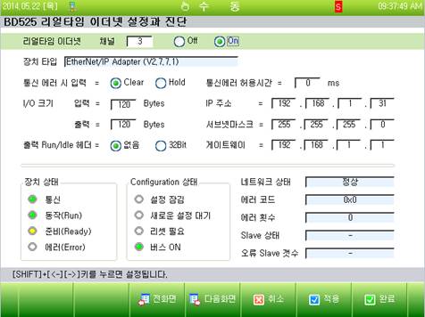
Figure 3.2 Ethernet/IP adapter setting screen
(3) Set the Ethernet information such as the IP address, the subnet mask and the gateway.

Figure 3.3 IP address setting screen
(4) This is to set the input data processing option and the output run/idle header option when an error with the input and output data or an error with the communication occurs.

Figure 3.4 I/O setting screen
n Input when a communication error occurs:
This is an option for handling input data (FB3.X) when an Ethernet/IP communication error occurs. When it is set as “Clear”, all the input data will be cleared to be “0” and when it is set as “Hold”, the last valid value that is to be generated when the error occurs will be maintained.
n I/O size:
This is for setting the size of input and output data when it comes to the Ethernet/IP scanner. When it comes to the robot controller, the input corresponds to FB3.Y and the output corresponds to FB3.X. The default of the size of the input and output data is 120Byte.
n Output run/idle header:
The BD525 Ethernet/IP adapter does not use the 32-bit run/idle header when exchanging I/O data with a scanner. If used normally, the install EDS files for Hi5a controller, select [None]
Without using the Hi5/Hi5a control EDS file, that is, the user prefers the Hi5/Hi5a controller using other company’s model that has 32-bit run/idle header, the 32 bit for the run/idle header (Refer to 3.3 RSLogix5000 Generic Ethernet Module Setting Example) shall be selected.
n Communication error allowed time.
Even when there is an error with communication, if the error does not exceed the allowed time, the “W0011 field bus network connection defective” error will not be generated and the field bus abnormal signal will not be generated.
(5) In order to use the Ethernet/IP adapter, shift it to the “On” position and then click the “Apply” or “Complete” button.

Figure 3.5 Function on/off setting screen
| After the setting is changed, click the『[F6]: Apply』button to reflect and save the change into the controller. In addition, if the setting is changed while the usage is at On state, the controller shall be reset or rebooted (Function reset: Usage On → Off → On) |
