3.1. BD525 EtherCAT Slave setting
3.1. BD525 EtherCAT Slave setting
Execute according to the following procedures to use the slave of the BD525 EtherCAT.
(1) Select 『[F2]: System』 → 『2: Control parameter』 → 『2: Input/Output signal setting 』 → 『14: BD525 real-time Ethernet setting and diagnosis 』.
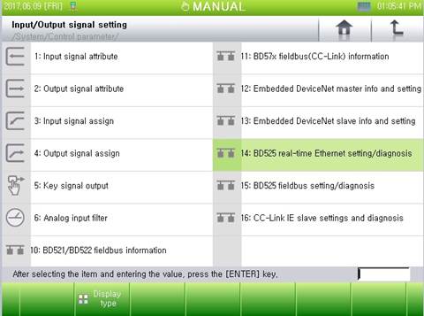
Figure 3.1 Menu of the BD525 Real time Ethernet setting and diagnosis
(2) Channel #3 is for the EtherCAT slaves. Input "3" in the channel input box, and press "Enter" or use the "[F3]: Previous" or "[F4]: Next" button to move to channel #3.
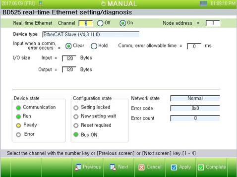
Figure 3.2 BD525 Real time Ethernet setting and diagnosis
(3) Set the information, such as the use, node address, input following a communication error, and I/O size, and press "[F6]: Apply" or "[F7]: Complete."
l Use: Set it as "On" to use the communication with a DeviceNet slave.
l Input following a communication error: This is an option for handling the input data (FB3.X) when there is a communication error. When it is set as "Clear," all the data will be cleared to 0 when a communication error occurs. If it is set as "Hold," the last effective value will be maintained when a communication error occurs.
l Node address: Effective range is 1 to 65535 for the unique Ids of Slave node.
l Time allowed for a communication error: Within the set time, a communication error will not generate an error/warning message. (0~65535 ms)
l I/O size:
∙ Input: Set the size of the input data (FB3.Y) by taking the master as reference (0–120).
∙ Output: Set the size of the output data (FB3.X) by taking the master as reference (0–120).
| Once the setting is changed, you should click the "[F6]: Apply" or "[F7]: Complete" button to reflect/save the change into the controller. In addition, if the setting is changed while the use is set as "On," the changed condition will be reflected after the device is reset or the controller is rebooted. |
