2.1. BD525 EtherCAT Master setting
2.1. BD525 EtherCAT Master setting
To set the network of the master of the BD525 EtherCAT, execute according to the following procedures. Sycon.net and the USB driver must be installed first before setting the EtherCAT Master network.
(1) Install the EDS file of the slave unit that needs to be installed to the master of the BD525 EtherCAT.
- Execute Network > Import Device Description
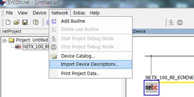
Figure 2.1 Sycon.net Import Device Description Menu
- In the Import Device Description dialog box, select "EtherCAT DDF" as the file type. After that, select the EDS file of the system that needs to be installed, and click the Open button.
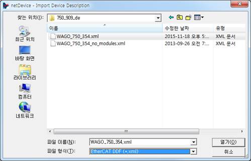
Figure 2.2 Installation of the Sycon.net ESI file
(2) Configuration of the EtherCAT network (insertion of the master and the slave)
- In the Device Catalog window, drag and drop "NETX 100 RE/ECM" into the bus line of the netDevice window.
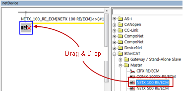
Figure 2.3 Insertion of the master
- In the Device Catalog window, drag and drop the slave units, which are to be connected, into the bus line. (This stage can be skipped when it is required to search the slaves connected to the master by scanning the network. Refer to (5) Slave Search.)
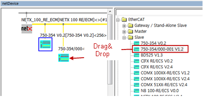
Figure 2.4 Insertion of the slaves
(3) USB-based connection between the BD525 board and Sycon.net
Connect the PC, in which Sycon.net is installed, and the BD525 board using a USB cable. If the USB driver is normally installed, you can see NETX 100 in Devices and Printer (in case of Windows 7).

Figure 2.5 USB Device
(4) Setting of the master connection driver
Open the DTM setting dialog box by double-clicking the master (NETX 100 RE/ECM) icon, and execute the following in sequence.
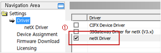
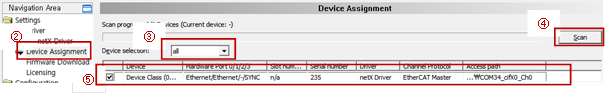
Figure 2.6 Setting of the master USB driver
① In Navigation Area, select Setting > Driver. Then, check the check box of the NETX Driver in the list of drivers on the left before clicking the Apply button.
② In Navigation Area, select Setting > Device Assignment.
③ In the Device Assignment screen on the right, change the Device Selection to "All".
④ Click the Scanbutton.
⑤ In the list of devices, check the check box of the EtherCAT master unit, and click the Apply button.
(5) Searching of a slave (Skip this stage when a slave was added manually in Stage (2).)
- Right-click the Master icon, and select the Connect menu.

Figure 2.7 USB communication connection
- When the USB connection is normal, the Master icon will turn green.
- Right-click the Master icon, and select the Network Scan ...menu.

Figure 2.8 Scanning of the network
- Of the searched slave nodes, change the Action of the devices that need to be added to the EtherCAT network to "Add," and click the Create Devices button.
∙ Action è Add : Adding a new node
∙ Action è Skip: No additional nodes.
∙ Action è Replace: Changing to the searched node
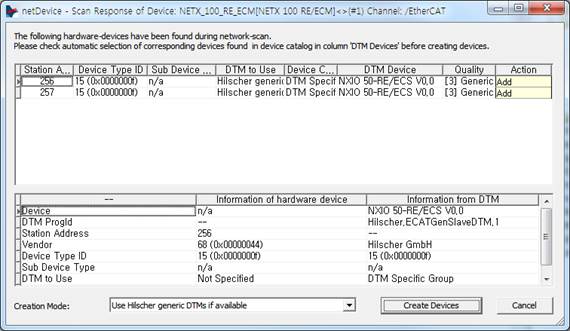
Figure 2.9 Dialog box for the network scanning result
(6) Setting of the slaves
- To change the slave settings, double-click the Slave icon to open the setting dialog box.
- Change the slave settings including Process Data, and then click the Apply button.
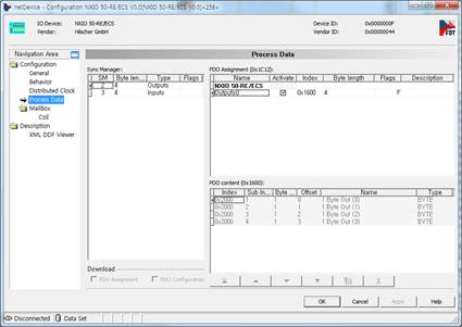
Figure 2.10 Setting of the slaves
(7) Setting of the master.
- In the off-line state, double-click the Master icon to open the setting dialog box.
(In the online state, right-click it and then select the Disconnect menu to change to the off-line mode.)
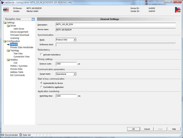
Figure 2.11 Setting of the master
(8) Download
- When all settings are completed, connect by right-clicking the Master icon, and select Download.

Figure 2.12 Setting of the master download
(9) Setting of the master of the BD525 EtherCAT of the robot controller
- Execute 『[F2]: System』 → 『2: Control parameter』 → 『2: Input/Output signal setting』 → 『14: BD525 Real-time Ethernet setting and diagnosis』.
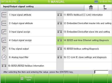
Figure 2.13 Menu of the BD525 Real-time Ethernet setting and diagnosis
- When there is an error with the sizes of the input and output data or with the communication, select the option of input handling, and click "[F6]: Apply" or "[F7]: Complete" button.
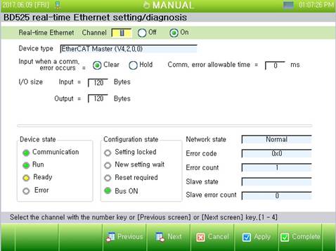
Figure 2.14 Setting and diagnosis of the BD525 Real-time Ethernet