3.2. Connect DeviceNet to the BD574 Board
3.2. Connect DeviceNet to the BD574 Board
Follow the next procedure to use the embedded DeviceNet master or slave function through the BD574 board.
(1) Connect the DeviceNet cable to the 5pin open-style connector of the BD574 board, as shown in the picture below.
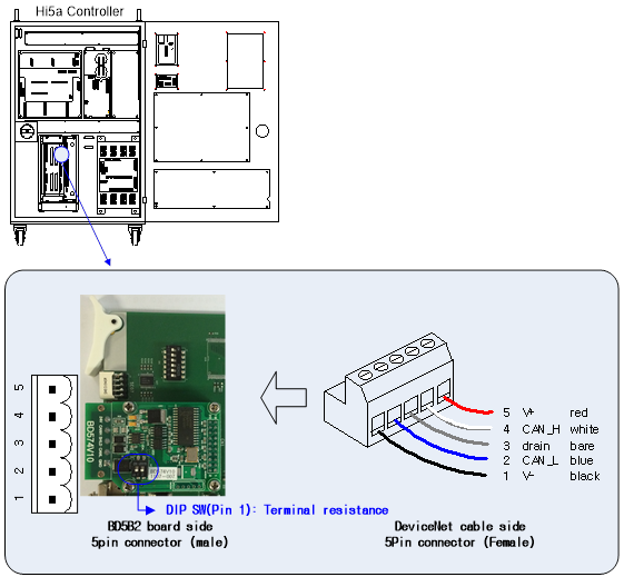
Figure 3.3 Connect DeviceNet to the BD574 board
Turn on the terminating resistor switch pin no.1 of the BD574 board when the Hi5a controller is the terminal of the DeviceNet network. It is not required to install it separately on the outside because the terminating resistor is mounted on the BD574 board.
Table 3‑1 BD574 terminating resistor switch
Switch No. | 1 | 2 | |
Setting Content | OFF | Embedded DeviceNet terminating resistor OFF | User CAN terminating resistor OFF |
ON | Embedded DeviceNet terminating resistor ON | User CAN terminating resistor ON | |
Switch appearance |
| ||

(2) Select CAN2(BD574) for the CAN port in the embedded DeviceNet setting of the teach pendant.
(Refer to “4.1. Embedded DeviceNet master Info and setting”, “4.2. Embedded DeviceNet Slave Info and setting”)

Figure 3.4 Select CAN2(BD574)